
Steampunk Harley - Tamiya 1/6 HD FLH Classic 'extreme' kit bash (Very Photo Heavy)
Page 8 of 25 •  1 ... 5 ... 7, 8, 9 ... 16 ... 25
 ![]()
Re: Steampunk Harley - Tamiya 1/6 HD FLH Classic 'extreme' kit bash (Very Photo Heavy)
![]() by KatsZenJammer Tue 06 Sep 2016, 1:55 am
by KatsZenJammer Tue 06 Sep 2016, 1:55 am

Well it's been a slow photo week meaning that I've been doing stuff but not the kind of stuff that makes for great visuals. But here's a few photos ...
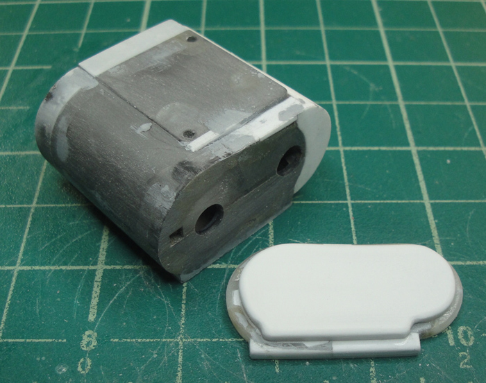
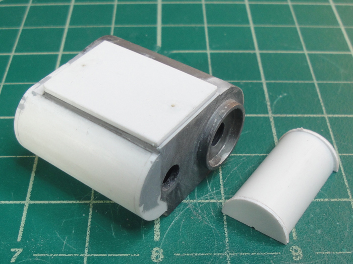
Cover plate modded some more. Right now these are baby steps in order to help solidify the underlying skeleton of the CVT more than anything. I'm starting to develop an idea of where I want to go with this ...
Added side covers to the extension of the CVT. These are just leftover circles from the discs I was cutting before, cut in half and shaped to fit before being affixed in place. I also had to trim off a bit on each side of the added curve.
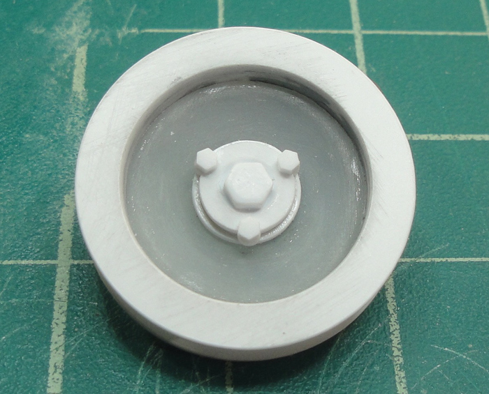
I asked myself why I chose to keep the one bit of kit detail, namely the fluid drain stopcock, and could not remember. Therefore, to facilitate ease of modding, I removed it as carefully as I could for further use.

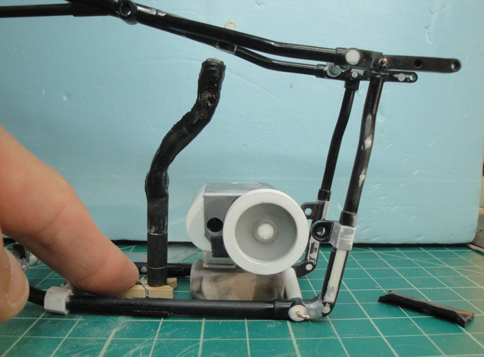
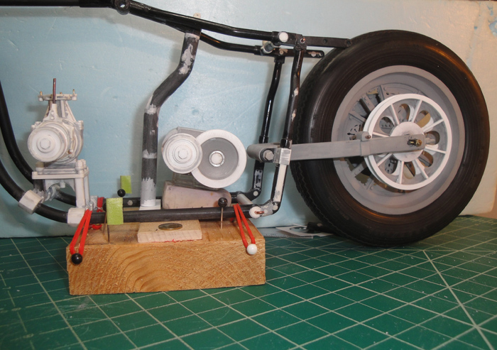
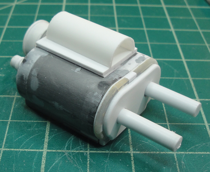
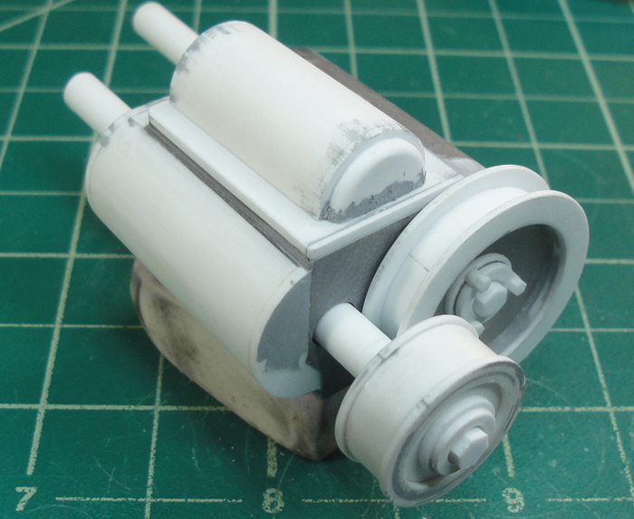
A rough look at the placement and alignment. The CVT will be sitting higher and this will necessitate the modding of the central seat post, I'm thinking of making it curved or eliminating it altogether.
And as thoughts have continued percolating there's the issue of the feed pump system which can be horrifically complex from what I've seen in my online research. So following suit with other complex parts I'm going to encase it thus eliminating the need to make the thing to begin with, lol. The drive belt to power the pump will be located on the other side of the CVT running off the primary drive shaft. This makes the most sense to me because if the cycle is idling in neutral the motor will still be running so the pump will still be required. I can kind of visualize it, hopefully soon I will be able to illustrate what I'm talking about by building it. And there will need to be lots of plumbing so any detail I sacrifice by shrouding it will be compensated for with all the feed tubes ... I hope, lol.
Just keep swimming ...

KatsZenJammer- Resident member

- Posts : 2600
Join date : 2016-05-20
Age : 57
Location : Vancouver, BC
Re: Steampunk Harley - Tamiya 1/6 HD FLH Classic 'extreme' kit bash (Very Photo Heavy)
![]() by Guest Tue 06 Sep 2016, 3:45 am
by Guest Tue 06 Sep 2016, 3:45 am

Guest- Guest
Re: Steampunk Harley - Tamiya 1/6 HD FLH Classic 'extreme' kit bash (Very Photo Heavy)
![]() by GaryDainton Tue 06 Sep 2016, 9:04 am
by GaryDainton Tue 06 Sep 2016, 9:04 am
More great work, a pleasure to watch.
GaryDainton- Advanced Member
- Posts : 4433
Join date : 2014-03-06
Age : 56
Location : Bolton UK
Re: Steampunk Harley - Tamiya 1/6 HD FLH Classic 'extreme' kit bash (Very Photo Heavy)
![]() by Geezerman Tue 06 Sep 2016, 11:16 am
by Geezerman Tue 06 Sep 2016, 11:16 am
I know the problem, I get into that situation often.
Loving following this build !!!


Geezerman- Advanced Member
- Posts : 3651
Join date : 2013-02-24
Age : 88
Location : Gulf coast of central Florids
Re: Steampunk Harley - Tamiya 1/6 HD FLH Classic 'extreme' kit bash (Very Photo Heavy)
![]() by KatsZenJammer Mon 12 Sep 2016, 12:32 am
by KatsZenJammer Mon 12 Sep 2016, 12:32 am
Gary - I ended up covering it with a 'plate' of sheet styrene to level the bottom of the CVT. I'll get into more detail later (which is to say I'll add more detail once I've figured out where it needs to go, lol).
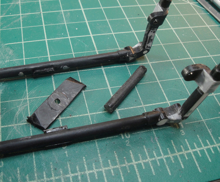
So the issue with the seat post comes up. After some thought I have decided to reshape it which means cutting it out, performing said re-shaping and modifying the mounts at top and bottom. Here's a shot of the seat post followed by the view after it was removed.


During the process of cutting away the bottom mount plate for the seat post the rearmost frame cross member popped free. Upon examination I recalled that it was a tad narrow (an original kit flaw) and I had compensated for it years ago by filling in the gap with CA which had gone brittle after a decade or more. So I decided to make a new one of the proper width.
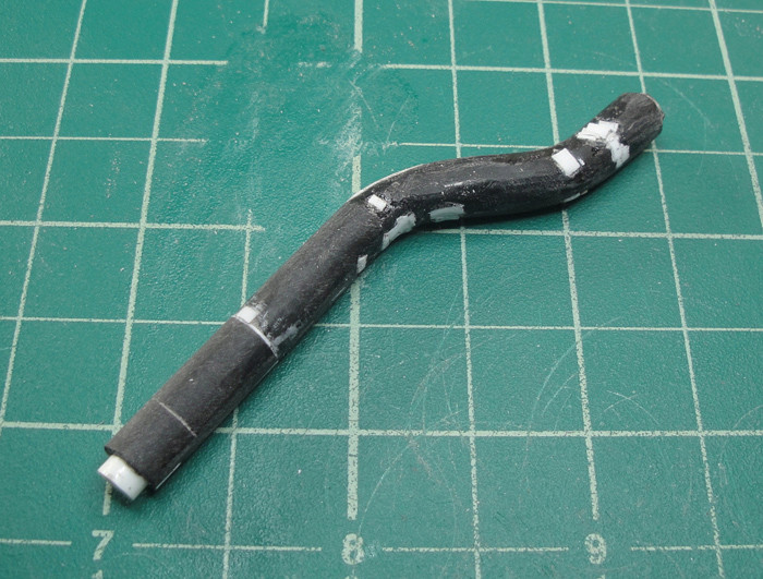
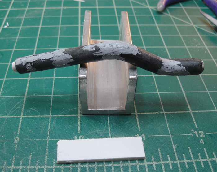
The saga of the seat post began with cutting it free, then realizing that it once had a 'working suspension' system for the original saddle. So I split the tube into its component parts, removed the inner details (piston and spring and such) and filled it with styrene rod. After the glue dried I set about shaping it with steam to start, but because this was a tube 'laminated' onto an inner core that proved to be problematic so I bit the bullet and hit it with good old fashioned fire. This was when the flaws in the plastic really became apparent as voids and casting bubbles spewed forth, resulting in the chewed Bic pen look of the roughly bent piece.
The cleaning up of the seat post - first step was to do a rough smoothing to give me an idea of the fill-in zones followed by filling in with bits of styrene. Let the glue dry then do some rough shaping then go back and fill in the stuff missed the first time through and repeat until satisfied.
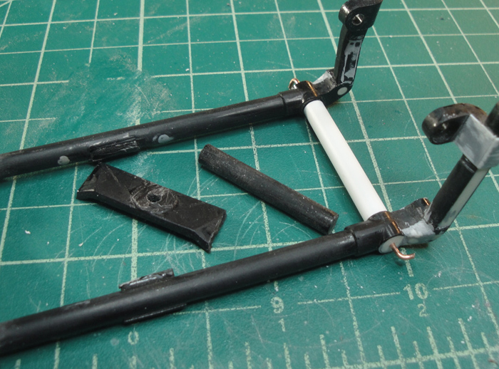
And then putty for the smoothing. The white rectangle is the blank for the bottom post mount.
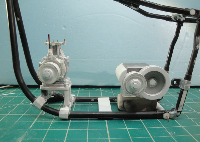
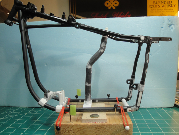
And a shot of the situation with the frame. The bottom post mount blank is now roughly sized. Also, I've added some of those dreaded hex nuts to the primary drive wheel/cogs.
So basically I need to get the seat post in place in order to be able to figure out how I'm going to mount the CVT and once I have that roughed out the CVT itself can have added detail like access plates and such. The nature of a CVT of this type is to not have a fluid lubricant reservoir so I won't be needing a drain spout/spigot. But I need to exercise patience here as there will be other stuff involved and going too fast on detailing the CVT might result in a cross-part conflict later.
Just keep swimming ...
Last edited by KatsZenJammer on Mon 12 Sep 2016, 2:36 pm; edited 1 time in total
KatsZenJammer- Resident member
- Posts : 2600
Join date : 2016-05-20
Age : 57
Location : Vancouver, BC
Re: Steampunk Harley - Tamiya 1/6 HD FLH Classic 'extreme' kit bash (Very Photo Heavy)
![]() by harron68 Mon 12 Sep 2016, 1:51 am
by harron68 Mon 12 Sep 2016, 1:51 am
harron68- Advanced Member
- Posts : 3616
Join date : 2013-02-28
Age : 73
Location : MIDWEST
Re: Steampunk Harley - Tamiya 1/6 HD FLH Classic 'extreme' kit bash (Very Photo Heavy)
![]() by Ace Mon 12 Sep 2016, 6:22 am
by Ace Mon 12 Sep 2016, 6:22 am

Ace- New Member

- Posts : 132
Join date : 2016-05-30
Re: Steampunk Harley - Tamiya 1/6 HD FLH Classic 'extreme' kit bash (Very Photo Heavy)
![]() by GaryDainton Mon 12 Sep 2016, 9:40 am
by GaryDainton Mon 12 Sep 2016, 9:40 am
GaryDainton- Advanced Member
- Posts : 4433
Join date : 2014-03-06
Age : 56
Location : Bolton UK
Re: Steampunk Harley - Tamiya 1/6 HD FLH Classic 'extreme' kit bash (Very Photo Heavy)
![]() by Skid Tue 13 Sep 2016, 10:29 am
by Skid Tue 13 Sep 2016, 10:29 am
_________________
Al.
Constructive criticism is always welcome.
“Success always demands a greater effort.” Winston Churchill
"Success is failure turned inside out" Unknown

Skid- Admin
- Posts : 7129
Join date : 2013-02-15
Age : 75
Location : Newcastle. Good Old Blighty. -

Re: Steampunk Harley - Tamiya 1/6 HD FLH Classic 'extreme' kit bash (Very Photo Heavy)
![]() by Geezerman Tue 13 Sep 2016, 11:52 am
by Geezerman Tue 13 Sep 2016, 11:52 am

This is the coolest detailed build !!
Enjoying it !
Geezerman- Advanced Member
- Posts : 3651
Join date : 2013-02-24
Age : 88
Location : Gulf coast of central Florids
Re: Steampunk Harley - Tamiya 1/6 HD FLH Classic 'extreme' kit bash (Very Photo Heavy)
![]() by Guest Sun 18 Sep 2016, 4:22 am
by Guest Sun 18 Sep 2016, 4:22 am
Guest- Guest
Re: Steampunk Harley - Tamiya 1/6 HD FLH Classic 'extreme' kit bash (Very Photo Heavy)
![]() by disabled modeler Sun 18 Sep 2016, 1:18 pm
by disabled modeler Sun 18 Sep 2016, 1:18 pm
...WOW..!....NICE work.
disabled modeler- Intermediate Member

- Posts : 979
Join date : 2016-05-22
Age : 60
Location : Quincy,IL. USA
Re: Steampunk Harley - Tamiya 1/6 HD FLH Classic 'extreme' kit bash (Very Photo Heavy)
![]() by Guest Sun 18 Sep 2016, 5:30 pm
by Guest Sun 18 Sep 2016, 5:30 pm
Guest- Guest
Re: Steampunk Harley - Tamiya 1/6 HD FLH Classic 'extreme' kit bash (Very Photo Heavy)
![]() by KatsZenJammer Thu 29 Sep 2016, 4:58 am
by KatsZenJammer Thu 29 Sep 2016, 4:58 am
A bit of a gap in posting due to the usual stuff, busy times and all that, but bits of stuff got accomplished here and there.
Cutting out little braces for the final drive wheel.
And in place. Next comes gap filling with tiny dabs of CA, some minor levelling, putty and sanding.
The modified seat post test fit and a rough check of how the tranny will sit. Alignment and height and all that are still TBD but within a small range which makes it easier.

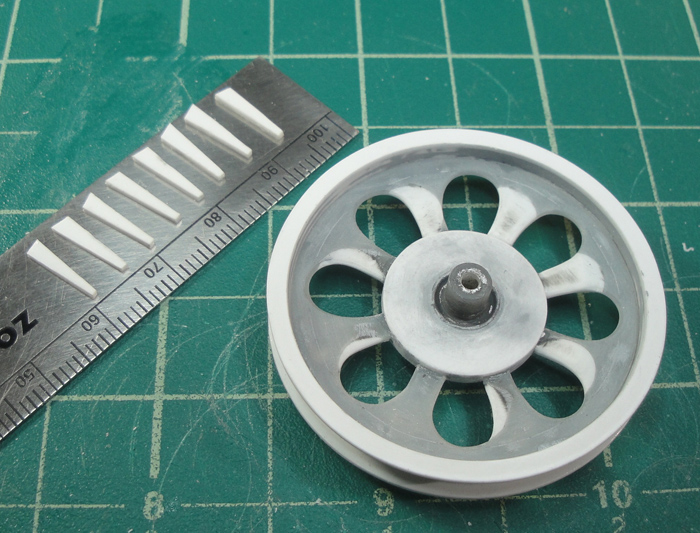
Working up the cover plate for the tranny. Instead of trying to create a whole new one I chose to chop up the perimeter of the kit one and use it to fill out the curves. To make things easier the shape of the tranny was traced onto a thin styrene sheet. Then the gaps were filled in with square rod and the odd bit of strip.
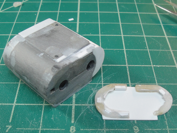
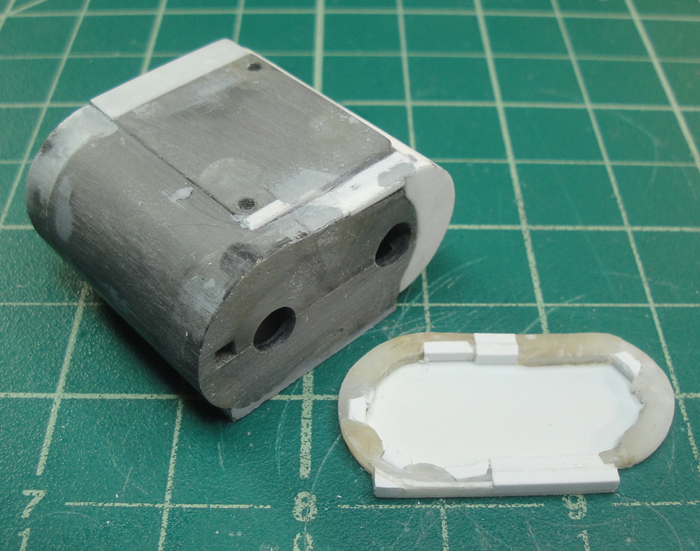
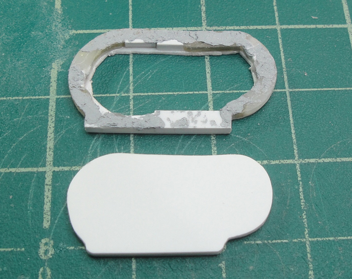
After the first part set up enough to file/putty the inner part of the sheet was cut away. The next piece is a simple step down of the outline of the first piece.
The seat post affixed in place.
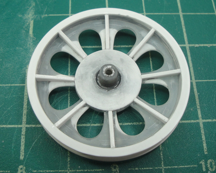
The cover plate after some slight shaping.
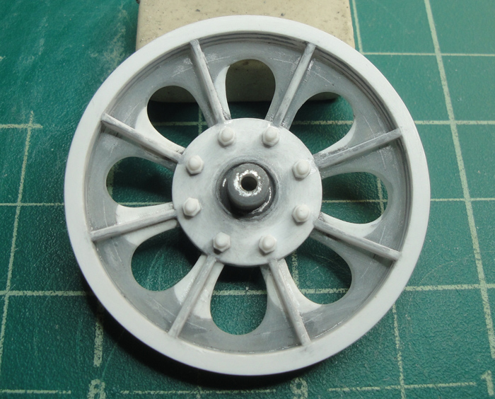
Adding some hex nuts *gasp!* to the final drive tranny wheel.
The cover plate after drilling, test fit. There's still more detail I want to add to the cover plate before I affix it to the tranny body. And the start of the 'shifting' mechanism for the tranny. I'd thought about Frankensteining the kit part but this way seemed easier.
The next aspect will involve the mounting assembly for the tranny, which has been waiting for the seat post mods in order to work out the placement. But this will be happening alongside the further detailing of the tranny, part of the process to insure the parts fit properly. Egads ...
Just keep swimming ...
KatsZenJammer- Resident member
- Posts : 2600
Join date : 2016-05-20
Age : 57
Location : Vancouver, BC
Re: Steampunk Harley - Tamiya 1/6 HD FLH Classic 'extreme' kit bash (Very Photo Heavy)
![]() by GaryDainton Thu 29 Sep 2016, 8:12 am
by GaryDainton Thu 29 Sep 2016, 8:12 am
GaryDainton- Advanced Member
- Posts : 4433
Join date : 2014-03-06
Age : 56
Location : Bolton UK
Re: Steampunk Harley - Tamiya 1/6 HD FLH Classic 'extreme' kit bash (Very Photo Heavy)
![]() by Mr Hirakawa Thu 29 Sep 2016, 8:20 am
by Mr Hirakawa Thu 29 Sep 2016, 8:20 am

Mr Hirakawa- Resident member
- Posts : 1530
Join date : 2015-11-11
Age : 52
Re: Steampunk Harley - Tamiya 1/6 HD FLH Classic 'extreme' kit bash (Very Photo Heavy)
![]() by Geezerman Thu 29 Sep 2016, 10:39 am
by Geezerman Thu 29 Sep 2016, 10:39 am
Mr Hirakawa wrote:This is simply outstanding work. To be able to come up with these ideas and then scratch build them to a very high standard is amazing. I am in awe of your efforts.
That pretty much sums it up for me also !!
I am so enjoying your work !!
Geezerman- Advanced Member
- Posts : 3651
Join date : 2013-02-24
Age : 88
Location : Gulf coast of central Florids
Re: Steampunk Harley - Tamiya 1/6 HD FLH Classic 'extreme' kit bash (Very Photo Heavy)
![]() by Skid Thu 29 Sep 2016, 10:45 am
by Skid Thu 29 Sep 2016, 10:45 am
 Superb as usual Kat's.
_________________
Al.
Constructive criticism is always welcome.
“Success always demands a greater effort.” Winston Churchill
"Success is failure turned inside out" Unknown
Skid- Admin
- Posts : 7129
Join date : 2013-02-15
Age : 75
Location : Newcastle. Good Old Blighty. -
Re: Steampunk Harley - Tamiya 1/6 HD FLH Classic 'extreme' kit bash (Very Photo Heavy)
![]() by KatsZenJammer Tue 11 Oct 2016, 3:45 am
by KatsZenJammer Tue 11 Oct 2016, 3:45 am
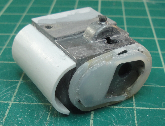
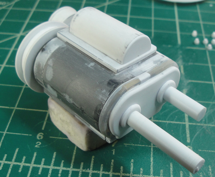
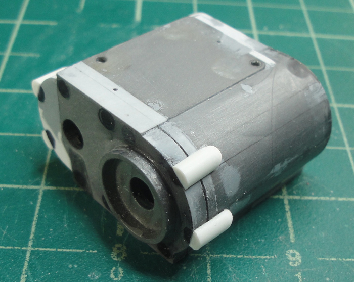
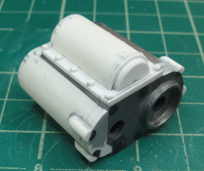
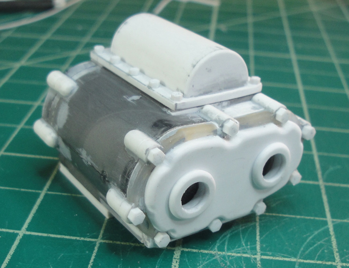
Well, got some stuff done but not a lot of photos - the usual reasons of lack of relevance and excitement. But here we begin with more work on the shift mechanism housing, adding sides to the half tube mostly.
After some more work the tube has a bit of extra form detail added and the edge of the plate has been made flush with the CVT body.
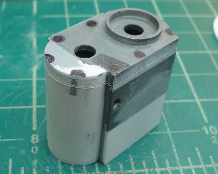
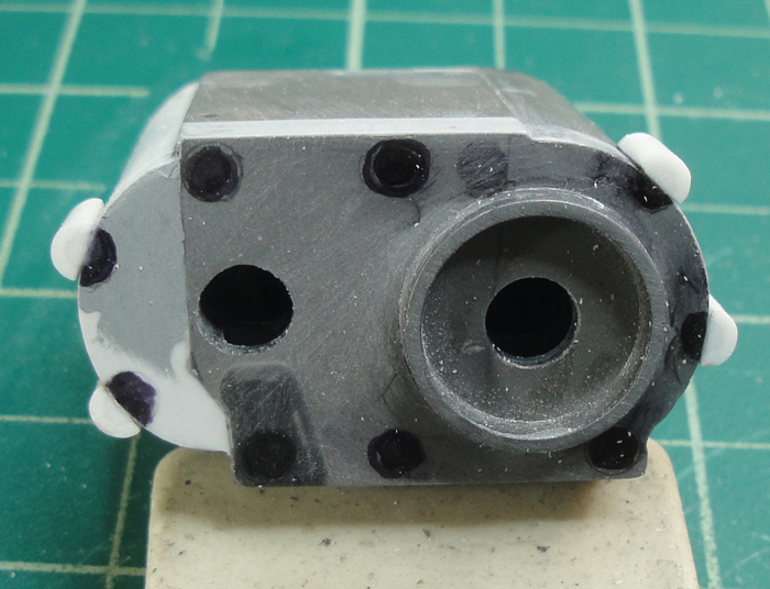
On the other side of the CVT I cut out rings which will be affixed to the cover plate once I align the shafts.
The black dots are rough placements for holes which will have inset hex nuts, though I already adjusted the placement since I took this photo. And you can see the scribing in of the 'seam' for the cover plate on that side of the CVT.
And while all that was going on I also made up nut and bolt combo's for the final drive cog/wheel. I actually tried to use a small metal nut as a die to scribe in threads on the bolt ends but couldn't find one of the correct diameter.
I wish I could report more progress but because it was the Thanksgiving holiday weekend in Canada I wound up spending the majority of my free time either preparing or consuming all manner of edibles that I would normally not trouble with. It is great to have a 'valid' excuse to over indulge, I must say, but it plays havoc with my ability to do detail work ... or pay attention to the world around me

KatsZenJammer- Resident member
- Posts : 2600
Join date : 2016-05-20
Age : 57
Location : Vancouver, BC
Re: Steampunk Harley - Tamiya 1/6 HD FLH Classic 'extreme' kit bash (Very Photo Heavy)
![]() by Geezerman Tue 11 Oct 2016, 11:09 am
by Geezerman Tue 11 Oct 2016, 11:09 am
Geezerman- Advanced Member
- Posts : 3651
Join date : 2013-02-24
Age : 88
Location : Gulf coast of central Florids
Re: Steampunk Harley - Tamiya 1/6 HD FLH Classic 'extreme' kit bash (Very Photo Heavy)
![]() by Skid Tue 18 Oct 2016, 12:23 am
by Skid Tue 18 Oct 2016, 12:23 am
_________________
Al.
Constructive criticism is always welcome.
“Success always demands a greater effort.” Winston Churchill
"Success is failure turned inside out" Unknown
Skid- Admin
- Posts : 7129
Join date : 2013-02-15
Age : 75
Location : Newcastle. Good Old Blighty. -
Re: Steampunk Harley - Tamiya 1/6 HD FLH Classic 'extreme' kit bash (Very Photo Heavy)
![]() by Guest Tue 18 Oct 2016, 1:59 am
by Guest Tue 18 Oct 2016, 1:59 am
May I make an observation and a suggestion on some past photos and work? I am not one to ever suggest or make suggestions without request. How ever your work is so exquisite and detailed, I fear that if I do not make an educated comment/suggestion I am not being fair to you or your awesome creative skills. I fear my silence of this observation may be a detriment to your finished project.
Guest- Guest
Re: Steampunk Harley - Tamiya 1/6 HD FLH Classic 'extreme' kit bash (Very Photo Heavy)
![]() by GaryDainton Wed 19 Oct 2016, 2:47 pm
by GaryDainton Wed 19 Oct 2016, 2:47 pm
GaryDainton- Advanced Member
- Posts : 4433
Join date : 2014-03-06
Age : 56
Location : Bolton UK
Re: Steampunk Harley - Tamiya 1/6 HD FLH Classic 'extreme' kit bash (Very Photo Heavy)
![]() by Skid Wed 19 Oct 2016, 3:16 pm
by Skid Wed 19 Oct 2016, 3:16 pm

_________________
Al.
Constructive criticism is always welcome.
“Success always demands a greater effort.” Winston Churchill
"Success is failure turned inside out" Unknown
Skid- Admin
- Posts : 7129
Join date : 2013-02-15
Age : 75
Location : Newcastle. Good Old Blighty. -
Re: Steampunk Harley - Tamiya 1/6 HD FLH Classic 'extreme' kit bash (Very Photo Heavy)
![]() by KatsZenJammer Wed 26 Oct 2016, 7:20 pm
by KatsZenJammer Wed 26 Oct 2016, 7:20 pm
Curt - I am deeply moved by your compliments and respect, thank you once again. As for comments, suggestions, criticism and everything else I have no issues with any input from anyone ... unless you want me to start over again that is
One thing I should make clear (or perhaps reiterate, I can't recall if I've said this before) is that this ridiculously complicated project is a first time thing for me. When I got back into scale modelling it was a first time attempt to rebuild a tall ship even though I had never built one from a kit - after I managed to complete that task I chose to start an even more complex and involved work. There are many times when I think I've bitten off way more than I can handle, hence the random delays and slow downs throughout the process. So any appearance of 'mastery' or 'expertise' on my part is simply the good fortune of having a plan come together. I should note that though I sometimes post my 'fails' in the WIP more often than not those 'fails' are undocumented ... and there are a lot of fails in this process, lol.
So - if anyone has anything they'd like to offer, critical, supportive or otherwise, it is all welcome because I'm travelling an unknown road and I'm making up the map as I go along.
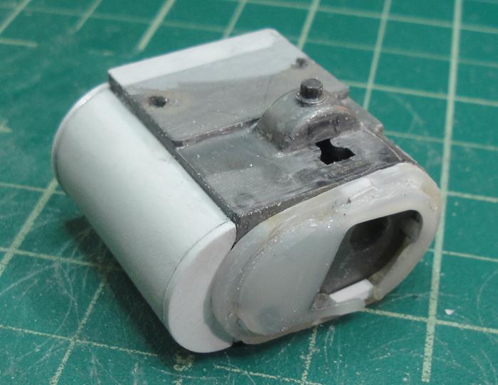
Speaking of delays, the gaps in my last few posts have widened a tad but I have also been getting time in here and there. We begin this post with a view of the transmission getting added detail.
The plate for the 'shifter' housing gets hex nuts.
And more detail to the other side of the tranny. These half round bits are all for the hex nuts.
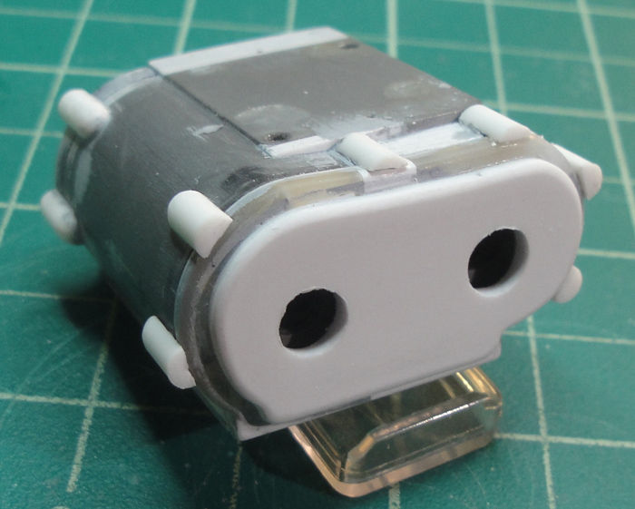
Notching the cover plate to accommodate the hex nuts.
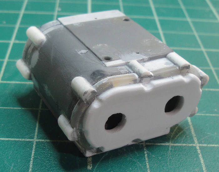
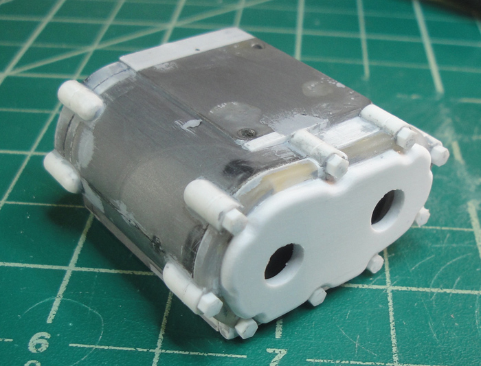
Carefully drilling out the insets for the hex nuts on this side.

Adding the hex nuts.
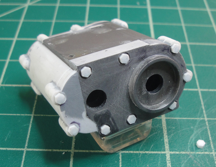
Affixing the 'rings' for the transmission shafts. The one on the left will be a 'stub' but the one on the right will have the shaft extend through to provide power for the recirculating water pump.
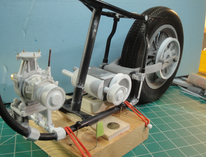
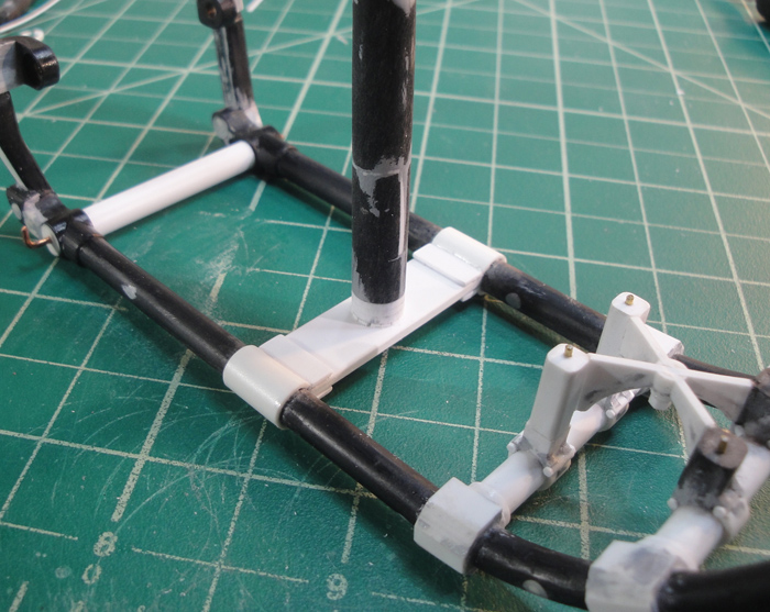
Coming back to the frame - here's the beginnings of the clamps for the seat post crossmember.
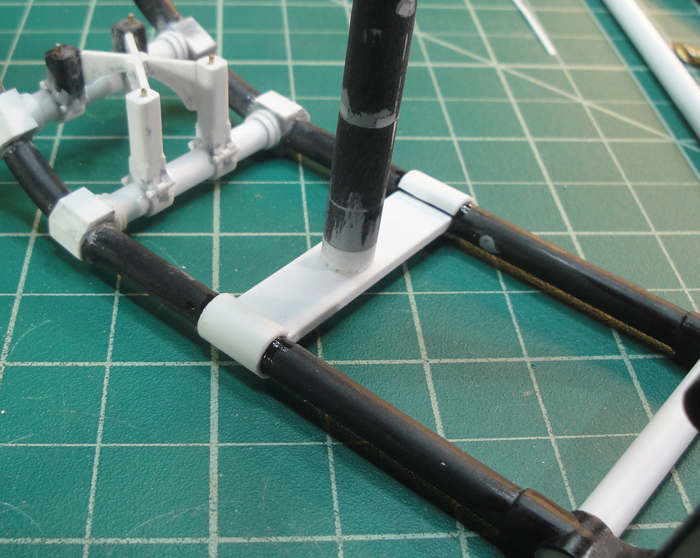
The start of the front mount point for the transmission - bare bones basics, there's a lot of work to be done here yet.

Adding tabs to the crossmember clamps.
I've reached the point where I have to build the mounts for the tranny and set it up to be in the proper place before I can continue. The height within the frame isn't a huge issue, but the side to side alignment is more tricky due to the fixed nature of the final drive cog/wheel on the rear tire. Once I have that 'locked down' then I have to work out the alignment of the primary drive cog and build a stabilizer for the primary cog on the transmission.
And then once I have the tranny in place and aligned I can begin working out the recirculating water pump and the shifting mechanism details.
Just keep swimming ...
KatsZenJammer- Resident member
- Posts : 2600
Join date : 2016-05-20
Age : 57
Location : Vancouver, BC
Re: Steampunk Harley - Tamiya 1/6 HD FLH Classic 'extreme' kit bash (Very Photo Heavy)
![]() by Sponsored content
by Sponsored content
Sponsored content
Page 8 of 25 • 1 ... 5 ... 7, 8, 9 ... 16 ... 25 ![]()
» Tamiya 1/6 Harley Davidson Fat Boy Lo
» Tamiya 1/6 Harley Davidson FLH1200
» Steampunk Ducati
» '57 Salvage bash-up
|
|
|