
SteamCycle Dio Base & Accessories
Skid's :: Works In Progress :: Dioramas
Page 3 of 6 •  1, 2, 3, 4, 5, 6
 ![]()
Re: SteamCycle Dio Base & Accessories
![]() by GaryDainton Sat 06 Jul 2019, 9:27 pm
by GaryDainton Sat 06 Jul 2019, 9:27 pm
GaryDainton- Advanced Member

- Posts : 4433
Join date : 2014-03-06
Age : 56
Location : Bolton UK

RetiredMike- Advanced Member
- Posts : 3525
Join date : 2013-04-27
Age : 73
Location : Valparaiso, Indiana


Geezerman- Advanced Member
- Posts : 3651
Join date : 2013-02-24
Age : 88
Location : Gulf coast of central Florids
Re: SteamCycle Dio Base & Accessories
![]() by KatsZenJammer Sat 13 Jul 2019, 6:21 pm
by KatsZenJammer Sat 13 Jul 2019, 6:21 pm

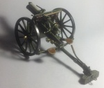
Gary - cool, it seems that you can get Anything on EBay, lol. If the base was bigger I'd be tempted to work in a fish 'n chips stand ...
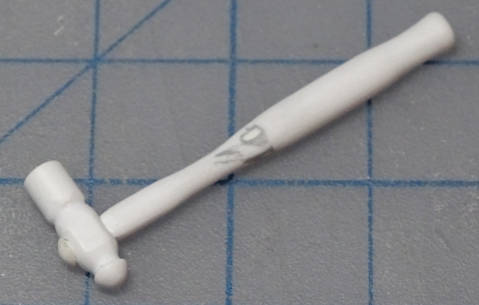
Bits of progress on the bits. The little wrench is 3/8 inch scaled to 1.5 mm - I was going to make a 1/4 inch wrench but now I'm thinking not as one of the nut drivers scales to that size and the pliers work in that range. Also the beginnings of the small hammer that every tool kit needs. This is based on a ball and peen finishing hammer in my own real tool kit and scaled accordingly. Both the handle and the head are worked from the same size styrene rod (3.2 mm). Basically just careful carving with X-Acto knives.

The initial idea of the hammer. Looking at this pic I realized the peen part was a tad long and the handle was a bit clunky so more adjustments came after.

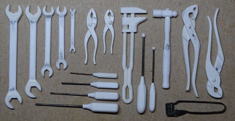
The wrenches and hammer after more work. The debate is whether to add more detail to the wrench handles in the form of insets and/or ridges along the edges - how much is too much ... The handle for the hammer has been smoothed out and the peen on the head has been reduced by about 0.75 mm.

And that's about it for the 'basic' tools at this point - wrenches (static and adjustable), screwdrivers, nut drivers, lots of pliers and a hammer covers the range I wanted. Still need to make a smallish 'igniter' rod for the burner (the current concept is a modified fireplace poker with an oily rag attached to one end). Some basic stuff like small push rods will be easy enough, these might fall by the wayside or not, we'll see.
Next comes the slightly more involved stuff like a small oiler can (lever style), possibly some small cans for extra water and two types of fuel (this is a 'maybe/maybe not' idea), and the tool rolls themselves. Probably two rolls, one larger for the bigger tools and a small one. Thinking about 'spare parts' as well, this will depend on if I can find some of the unused experiments from the steamcycle build.
After that, or maybe even during, will come the elaborate accessories like gloves/gauntlets, goggles, maybe a riding hat or helmet and the weaponry which is kind of de rigueur for the steampunk theme. The ambitious concept was for a rifle, pistol, sword and knife but further reflection has modified that to a large knife, kind of bayonet style but not as long as a sword, and a sidearm pistol but no rifle. This decision was made for purely practical reasons - though it may seem all cool and romantic having a long rifle and sword on a motorcycle is logistically unrealistic in terms of geometry. Also, there is the consideration of where all this stuff would be slung, stored and otherwise carried on the steamcycle.
Maybe it's time to consider a backpack ...
Oh, and if anyone has any ideas about stuff I haven't mentioned or included feel free to toss it into the ring - I'm not a motorcycle rider so there's lots of practical considerations I have probably missed.

KatsZenJammer- Resident member
- Posts : 2600
Join date : 2016-05-20
Age : 57
Location : Vancouver, BC
Re: SteamCycle Dio Base & Accessories
![]() by GaryDainton Sun 14 Jul 2019, 1:11 pm
by GaryDainton Sun 14 Jul 2019, 1:11 pm
https://www.deviantart.com/shaitandrac/favourites/45482655/Steampunk-Weapons
GaryDainton- Advanced Member
- Posts : 4433
Join date : 2014-03-06
Age : 56
Location : Bolton UK
Re: SteamCycle Dio Base & Accessories
![]() by Guest Tue 16 Jul 2019, 1:31 pm
by Guest Tue 16 Jul 2019, 1:31 pm
For as long as I live, and my memory continues to work, I will never forget this build.
I have even taken screen shots and created a picture file just for your project. It really is a master piece of art.

Last edited by Plastic Freak on Sun 21 Jul 2019, 3:33 am; edited 1 time in total
Guest- Guest
Re: SteamCycle Dio Base & Accessories
![]() by Skid Tue 16 Jul 2019, 6:45 pm
by Skid Tue 16 Jul 2019, 6:45 pm

_________________
Al.
Constructive criticism is always welcome.
“Success always demands a greater effort.” Winston Churchill
"Success is failure turned inside out" Unknown

Skid- Admin
- Posts : 7128
Join date : 2013-02-15
Age : 75
Location : Newcastle. Good Old Blighty. -

Re: SteamCycle Dio Base & Accessories
![]() by KatsZenJammer Sun 21 Jul 2019, 12:21 am
by KatsZenJammer Sun 21 Jul 2019, 12:21 am
Gary - thanks for that link. I've mostly been browsing Pinterest up to now, must remember DA for future reference.
Curt - thanks for finding a much more respectable way to describe what's going on with me (usually I use terms like obsessive, compulsive, neurotic, nit picky and just plain stupid, lol).
The small hammer done for now. I shifted from a wood handle to metal, so the handle top is now rounded like a bolt head.
The hand tools arrayed. Also included is the sparker for the lamps made a few years ago. Next comes the paint for all the plastic stuff.
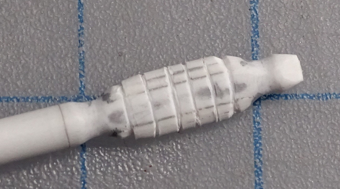
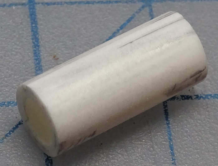
The beginnings of the 'lighter rod' and the oiler can. I don't know the proper name for it, but the lighter rod is modelled after a fireplace poker but instead of a half-a-fleur-di-lys looking poker end it's going to have a wad of oily fabric. The concept is that to light the boiler/burner one has to light one of the lamps with the sparker, then light the wad of oily rag, then stick that into the lighter hole on the right side of the boiler/burner. The oiler can body is 6mm styrene tube thickened with 2 layers of cut down larger tube slit and curled in to fit. The gap is in case I want to add a seam on the side ... still pending.

The handle of the lighter rod after some carving, additions, grooving and so forth. Again this is being worked up 'on the source rod' to make manipulating it easier.
The body of the oiler can sans seam. Diameter roughly 8 mm.
The lighter rod after some more work. The handle has been cut from the source rod at this point and the end of the rod proper had been thickened slightly with strips of thin styrene.

Missed a step where I drilled out the end of the rod and added a bit of smaller styrene rod to affix the oily wad material to. Then came the process of figuring out what material would work best for the oily wad which is meant to be lit on fire and in the end I went with some cotton from a Q-Tip affixed with PVA (aka white glue). I'm going to tap very tiny amounts of super thin CA to insure the bond. So, basically, this is a large (scale just over a foot), fancy, flaming Q-Tip, lol.

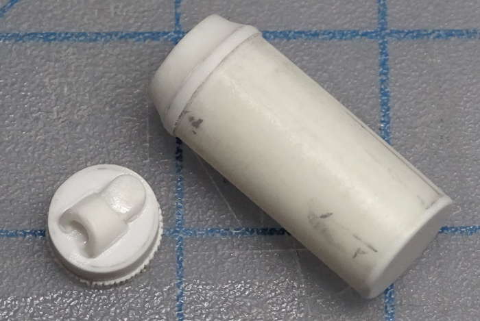
The oiler can body bottom is sealed and the top is set up for an indent. Also, the cap takes form, where the pump and the spigot will sit. Still debating the form of the spigot but I want to stay away from modern style flexible style designs.

And it wouldn't really be part of the overall concept if I didn't start having second thoughts - this time it's the sheer amount of stuff I need to find a place for on the Steamcycle. But I'm going to call that uncertainty and try to keep on heedlessly careening down this vague and undefined path. After all, in the world of scale modelling it's all about imagination even when the goal is reality.
Time to change my signature ...
KatsZenJammer- Resident member
- Posts : 2600
Join date : 2016-05-20
Age : 57
Location : Vancouver, BC
Re: SteamCycle Dio Base & Accessories
![]() by GaryDainton Sun 21 Jul 2019, 5:09 pm
by GaryDainton Sun 21 Jul 2019, 5:09 pm
GaryDainton- Advanced Member
- Posts : 4433
Join date : 2014-03-06
Age : 56
Location : Bolton UK
Re: SteamCycle Dio Base & Accessories
![]() by Johnag Sun 21 Jul 2019, 7:44 pm
by Johnag Sun 21 Jul 2019, 7:44 pm
WOW, you are taking this piece of art to a new level Sir, your detailing is out of this world...

Andy...
_________________
Andy...
Life isn't about how to survive the storm, but how to dance in the rain...

Johnag- Moderator

- Posts : 1576
Join date : 2013-10-12
Age : 58
Location : North Wales, U.K... -
Re: SteamCycle Dio Base & Accessories
![]() by RetiredMike Mon 22 Jul 2019, 1:25 pm
by RetiredMike Mon 22 Jul 2019, 1:25 pm
RetiredMike- Advanced Member
- Posts : 3525
Join date : 2013-04-27
Age : 73
Location : Valparaiso, Indiana
Re: SteamCycle Dio Base & Accessories
![]() by KatsZenJammer Tue 23 Jul 2019, 10:54 pm
by KatsZenJammer Tue 23 Jul 2019, 10:54 pm
Got some extra crafting going on due to a bum shoulder which is keeping me home. Not serious but as I have a manual labour day job the physical considerations are more prominent. It's also curtailing my computer time due to the logistics being uncomfortable - but I can (and do) fiddle with plastic bits without any issues so here we go ...
The oiler can body after more shaping and stuff and the cap with the start of the pump assembly in place. Note, the ridged edge at the bottom of the cap was achieved the old fashioned way of careful knife and pin scraping ... a lot of pin scraping.
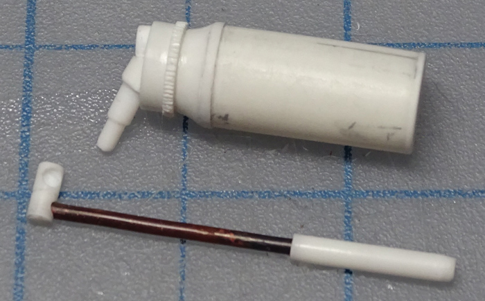
The pump assembly taken to a stop point, the cap affixed to the body and the spigot takes form. I didn't want to make a modern style gooseneck (bendy spiral metal, we've all seen it) so an old fashioned hinge-style folding spigot was called for. Spigot tube is a piece of 18 gauge copper wire and the long bit of styrene rod is for the nozzle.
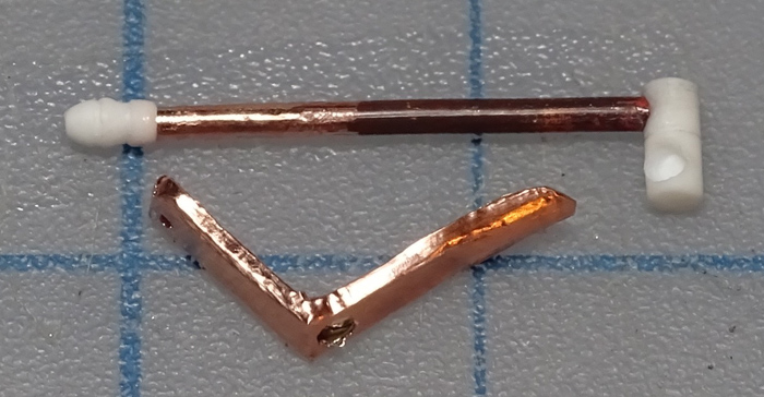
The pump lever was formed from the thin frame portion of PE detailing for an IJN battleship. First the sides were bent over, using a chunk of 2mm styrene square rod for the forming. Then the hole for the pump spigot feed was drilled through. Then it was bent and the fold for the back was worked in.

The 'bottom' of the lever shaped and curved.

The spigot nozzle tip formed from styrene rod - when possible I use a small drill vise for ease of control.

The spigot with completed plastic bits and the pump lever covered with self-adhesive copper foil. The foil was added to increase the thickness of the PE just a touch.
And an oiler ready for painting. The metals parts were affixed using medium thick CA. The only thing I might add is a few dents in the can to 'age' it somewhat ... or maybe not.

Next up on the plate are some weapons - namely a knife and a Steampunk-y pistol of some sort. Though there are plans and reference photos for both I'm feeling the urge for some improvisation so we'll have to see what happens with those.
KatsZenJammer- Resident member
- Posts : 2600
Join date : 2016-05-20
Age : 57
Location : Vancouver, BC
Guest- Guest
GaryDainton- Advanced Member
- Posts : 4433
Join date : 2014-03-06
Age : 56
Location : Bolton UK
Geezerman- Advanced Member
- Posts : 3651
Join date : 2013-02-24
Age : 88
Location : Gulf coast of central Florids
RetiredMike- Advanced Member
- Posts : 3525
Join date : 2013-04-27
Age : 73
Location : Valparaiso, Indiana
Re: SteamCycle Dio Base & Accessories
![]() by KatsZenJammer Sat 27 Jul 2019, 4:50 pm
by KatsZenJammer Sat 27 Jul 2019, 4:50 pm
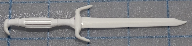
This post is all about a knife, or maybe dagger is a more accurate term.
Starting with the blade, this is roughly 8 1/2 inches long in scale. The inner base shape was formed from 0.5 mm sheet and includes the tang. The thickening on the sides is also 0.5 mm sheet styrene. Shaping and forming was done using a curved knife blade initially.

The crosspiece blank formed from 2 mm square rod. Can't really see it here but a channel for the tang was drilled through then cleaned up with a #11 X-Acto blade.

The handle blank takes form - two pieces cut from 0.75 mm sheet and spacers cut from 0.5 mm sheet to form the groove for the tang.

Test fit and everything seems to be going smoothly.

Carving and shaping ... and somewhere during the process the tang snapped off, lol. This was to be expected and isn't really a set back as the tang was there mostly for the initial alignment.

Further development to the handle and crosspiece. To secure the smaller plastic detailing I used MEK for the initial gluing then followed up with thin CA for strengthening.

The 'personality' of the dagger emerges. The ridges on the handle are rough because the plan is to wrap that portion of the handle with cord after initial painting. The 'blade catcher' spikes on the crosspiece aren't what I had originally planned but a lot of reference material I saw has similar designs and this seemed easier and more practical than some of the more ornate, swirly designs I had in mind.

The dagger is almost at the 'done for now' stage, pics of that in the next post. Also being developed is the pistol which will be featured in the next post.
Getting to the point where the considerations are going to shift to wardrobe bits, namely goggles and gauntlets. The consideration here is the lack of recent experience with 'soft' materials so I might hold off on starting these and get in some practical exercise with the tool rolls and such. A shout out to Gary for past references as far as potential building materials goes.
And then there's the frame for the base ... gotta get around to that soon ...
KatsZenJammer- Resident member
- Posts : 2600
Join date : 2016-05-20
Age : 57
Location : Vancouver, BC
Re: SteamCycle Dio Base & Accessories
![]() by Guest Sat 27 Jul 2019, 6:32 pm
by Guest Sat 27 Jul 2019, 6:32 pm
Guest- Guest
Re: SteamCycle Dio Base & Accessories
![]() by GaryDainton Sun 28 Jul 2019, 11:25 am
by GaryDainton Sun 28 Jul 2019, 11:25 am
GaryDainton- Advanced Member
- Posts : 4433
Join date : 2014-03-06
Age : 56
Location : Bolton UK
Re: SteamCycle Dio Base & Accessories
![]() by RetiredMike Mon 29 Jul 2019, 2:15 pm
by RetiredMike Mon 29 Jul 2019, 2:15 pm
RetiredMike- Advanced Member
- Posts : 3525
Join date : 2013-04-27
Age : 73
Location : Valparaiso, Indiana
Re: SteamCycle Dio Base & Accessories
![]() by KatsZenJammer Mon 29 Jul 2019, 7:53 pm
by KatsZenJammer Mon 29 Jul 2019, 7:53 pm
The dagger at the 'done for now' stage. Further development has been halted because I want to work up the pistol first then come back to this when the embellishment detailing begins.
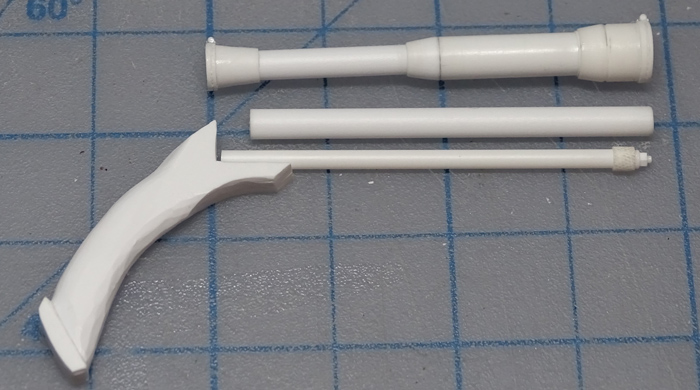
Speaking of pistols, the first piece of it is, of course, the barrel. This is 3.2 mm styrene round rod and the choice for projectile size is 9mm so the bore was scaled accordingly at 1.5 mm.

After many months of debating the choice of iron sights or optical scope the winner was the scope for the simple reason that a big scope on a pistol looks more Steampunk-y. 3.2 mm and 5 mm rod pieces were used for the initial blank forming.

The scope starts to develop its shape and the eyepiece makes its appearance.

Missed a few steps but the scope is now at the 'stop' stage until it's time to figure out how to mount it to the pistol proper. To avoid having to actually make lenses I went the easy route of closed lens covers on hinges. At the bottom is the ammo tube.

The handle of the pistol appears. The concept for the pistol has morphed and mutated over time - at this point its a hybrid of a classic flintlock duelling pistol with all kinds of alternate additions, such as the ammo tube and scope.
The initial trigger concept and the basis for the trigger guard. Making the trigger from styrene was fun ... no it wasn't, lol. This is the third or fourth version as the previous ones flew away into the ether whilst being worked on. The guard is annealed 18 gauge copper wire flattened and shaped with jewelry pliers of various types.

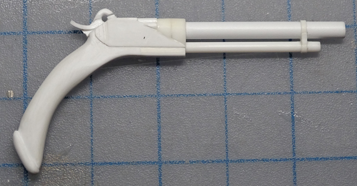
More development, the ammo tube is now affixed and the 'stock' of the pistol body begins to form. The trigger guard initial concept is a bit big, the plan is to reduce it slightly.

The barrel has a mount point and the next iteration of the trigger takes shape. The plastic trigger was just too chunky and so the redo involved copper wire annealed, flattened and shaped. Still in progress.

Side panels coming up. There is a spacer tab (which will be hidden) for the barrel.

The barrel is affixed and the side and top panels as well.

Throughout the whole Steamcycle project there has been the pendulum swing between 'plausible realism' and 'Steampunk magic/tech' and usually the plausible realism side has won out. For the pistol I'm trying to push the pendulum more to the magic/tech end because, frankly, there isn't enough of that side of the Steampunk thing and an ideal place for this is the sidearm - an essential part of the Steampunk wardrobe.
So, the basis started with a flintlock duelling pistol which was given an ammo tube (inspired by old rifles like the Winchester '73). The next steps are to add more weirdness in the form of a binary propellant system instead of black powder, two small tanks which will sit under the ammo tube. There will be a hammer to ignite the propellant. The concept I'm using to guide the evolution is that when the hammer is cocked this injects a small amount of the binary propellant into the firing chamber, hammer falls and the propellant explodes driving the projectile (ball shot, not tapered bullets). Part of the combustion gas is vented to the ammo tube which drives the next ball into the firing chamber. So there will be plumbing, which makes and firearm look Steampunk-y. This is a single shot - no double action or sliding bolt action stuff. And the plan is to make a 'reload' set of tanks for the binary fuel propellant tanks.
Things had to get weird eventually.
KatsZenJammer- Resident member
- Posts : 2600
Join date : 2016-05-20
Age : 57
Location : Vancouver, BC
RetiredMike- Advanced Member
- Posts : 3525
Join date : 2013-04-27
Age : 73
Location : Valparaiso, Indiana
Re: SteamCycle Dio Base & Accessories
![]() by KatsZenJammer Wed 31 Jul 2019, 6:21 pm
by KatsZenJammer Wed 31 Jul 2019, 6:21 pm
Taking advantage of the injury-imposed downtime from the day job - progression occurs.
Test fit shot with the barrel/tube brace near the front.

The binary propellant tanks take form, though they kind of look like elongated Tic-Tacs at this point. The pistol body also starts to take more form.

The hammer takes form. This will be static so the blank is set into a slot cut into the body. You can see the pencil outlines still on the plastic. Also, more body detail - I was inspired to give it a fake revolver kind of look.

Development of the hammer. The striker front portion was thickened on either side and the rear bit was formed from a portion of 10 mm styrene tube.
Oblique top view of the hammer a bit later in development.

The mounting zone for the propellant tanks which doubles as an ammo tube brace.

The scope mount zone aka barrel brace in place.
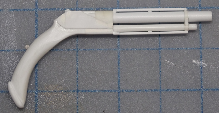
Test fit of the stuff developed so far. The trigger guard has been streamlined a bit as it seemed too chunky and big.

And after looking at the photos I realized that the handle was a tad too long so I sawed 3 to 4 mm off the butt.

Reshaped the butt and re-attached.

These posts have been deceptive because they give the impression that I'm working quickly - and this is most assuredly not the case, lol.
Next up is figuring out the mounting for the scope and adding more details to the scope once that's figured out. As well the mounting for the propellant tanks which will involve the capability of quick removal and reload. There is also a vague concept forming for a shroud or some sort of 'over structure' for the open barrel zone. And plumbing ...
KatsZenJammer- Resident member
- Posts : 2600
Join date : 2016-05-20
Age : 57
Location : Vancouver, BC
Re: SteamCycle Dio Base & Accessories
![]() by GaryDainton Thu 01 Aug 2019, 6:20 am
by GaryDainton Thu 01 Aug 2019, 6:20 am
GaryDainton- Advanced Member
- Posts : 4433
Join date : 2014-03-06
Age : 56
Location : Bolton UK
Re: SteamCycle Dio Base & Accessories
![]() by Guest Thu 01 Aug 2019, 2:24 pm
by Guest Thu 01 Aug 2019, 2:24 pm
Guest- Guest
Page 3 of 6 • 1, 2, 3, 4, 5, 6 ![]()
» Steampunk Harley - Tamiya 1/6 HD FLH Classic 'extreme' kit bash (Very Photo Heavy)
» A Steamcycle - an extreme kit bash/scratch build
Skid's :: Works In Progress :: Dioramas
|
|
|