Steampunk Harley - Tamiya 1/6 HD FLH Classic 'extreme' kit bash (Very Photo Heavy)
Page 17 of 25 •  1 ... 10 ... 16, 17, 18 ... 21 ... 25
 ![]()
Re: Steampunk Harley - Tamiya 1/6 HD FLH Classic 'extreme' kit bash (Very Photo Heavy)
![]() by webby Wed 20 Dec 2017, 11:36 am
by webby Wed 20 Dec 2017, 11:36 am
webby- Moderator

- Posts : 2194
Join date : 2013-02-27
Age : 64
Location : Strathpine Australia. Built over WW2 airstrip
Re: Steampunk Harley - Tamiya 1/6 HD FLH Classic 'extreme' kit bash (Very Photo Heavy)
![]() by Guest Wed 20 Dec 2017, 9:13 pm
by Guest Wed 20 Dec 2017, 9:13 pm
Guest- Guest
Re: Steampunk Harley - Tamiya 1/6 HD FLH Classic 'extreme' kit bash (Very Photo Heavy)
![]() by KatsZenJammer Tue 02 Jan 2018, 12:00 am
by KatsZenJammer Tue 02 Jan 2018, 12:00 am

Well, a bit of a hiatus interspersed with bouts of work bench time and me losing track of the number of pictures I was taking leads to a longer than average post - but hey, it's my first post of 2018 so why not.
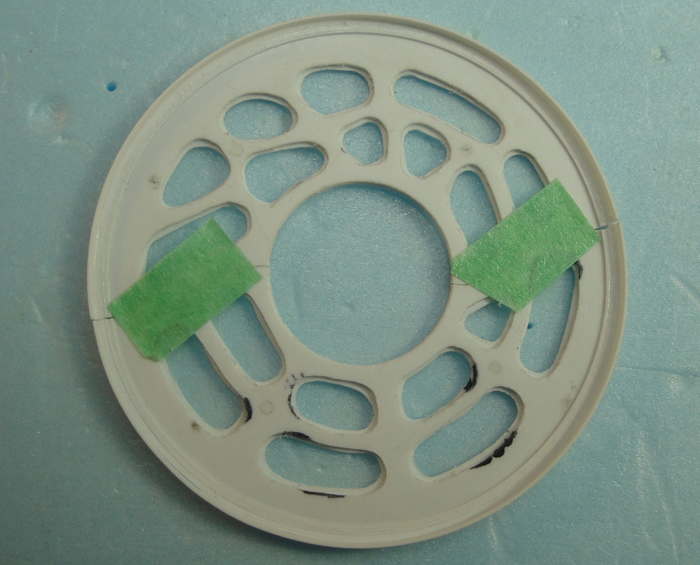
So we return to the flywheel shroud - here it is after I've increased the outside diameter by adding strips of styrene. This is an example of my sometimes inaccurate measurements resulting in additional work being needed.

Once the diameter was what I wanted I added a wider strip along the perimeter as a base for further work.
On the top left is what will become a border ring for the shroud face. Top right is the other side of the shroud with a lip of wider styrene to allow for edge work.
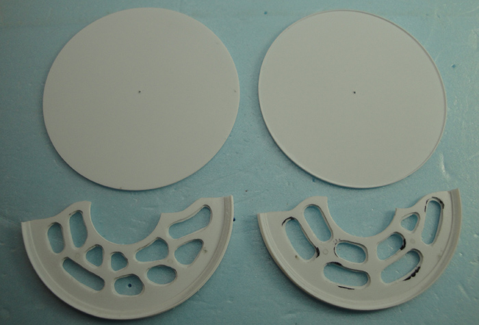
On the left is the backside of the shroud and on the right is the border for the shroud face after the inner circle had been cut out.
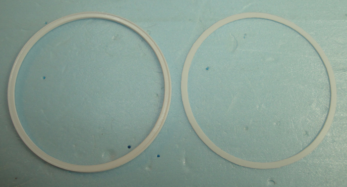
The shroud face with the border added.

The shifter sees some work as well, here's a check fit of the first shift lever.

A view of the back to show how the post is seated within.

The second shift lever mount piece being worked up on the end of a styrene post. This method is much easier than trying to work the small bit freehanded.
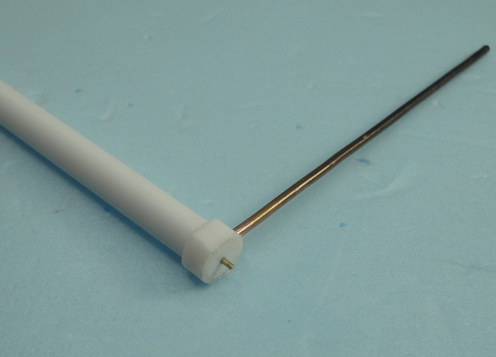
Check fit of the second shift lever. Also the first shift lever has had some bends put in.

Playing with curves and styles for the second shift lever. This version has already been altered since I took this photo.

Back to the flywheel shroud - after quadruple checking the measurements I affixed spacer posts to the back side ring with MEK. At this point the mesh inserts were also affixed with CA into the shroud face.

Then I attached the face to the back using just MEK at this point.

Test/check fits on the flywheel. This is the upper half and so it is not sitting properly but the basic idea is now visible.


The lower half of the shroud gets a similar treatment. Due to the geometry of the placement I couldn't give the lower part a half circle back ring but a quarter circle would fit without problem. The open part will have custom stuff as that's where I'll add frame mounts.
I'm still trying to work out how I want to mount the primary drive belt shroud which is why that part has been unseen these past weeks.
The likely future is that I'll be working on the mounting for both shrouds at the same time because to do so I'll have to remove a bunch of parts to get access to the frame sections. Also, I'm wondering about if the shift levers should have some sort of ratchet lock lever thingy - which might be problematic as I've bent the rods in such a way that there is no straight line and thus a simple post and rocker lever won't work. I'm considering tossing this concern into the 'Magic' part of Steampunk and not bothering ... though the additional mechanical bits would look cool.
Thankfully these parts have managed to consume enough of my active attention that I haven't started developing yet more parts that I'm not sure about - I know I need to work up the 'flame throttle' for the burner as well as the water pump which will be powered off the primary drive shaft at the transmission but, really, I should wait until the current parts have been mostly finalized.
And I'm changing to a new end post slogan for 2018 ... candidates included, "What the hell am I thinking?" and "Am I really this stupid?" But after some consideration I've decided on ...
Nothing exceeds like excess ...

KatsZenJammer- Resident member

- Posts : 2600
Join date : 2016-05-20
Age : 57
Location : Vancouver, BC
Re: Steampunk Harley - Tamiya 1/6 HD FLH Classic 'extreme' kit bash (Very Photo Heavy)
![]() by GaryDainton Tue 02 Jan 2018, 4:21 pm
by GaryDainton Tue 02 Jan 2018, 4:21 pm
If you can engineer them into your current design.


GaryDainton- Advanced Member
- Posts : 4433
Join date : 2014-03-06
Age : 56
Location : Bolton UK
Re: Steampunk Harley - Tamiya 1/6 HD FLH Classic 'extreme' kit bash (Very Photo Heavy)
![]() by Geezerman Sun 07 Jan 2018, 12:02 pm
by Geezerman Sun 07 Jan 2018, 12:02 pm


Geezerman- Advanced Member
- Posts : 3651
Join date : 2013-02-24
Age : 88
Location : Gulf coast of central Florids
Re: Steampunk Harley - Tamiya 1/6 HD FLH Classic 'extreme' kit bash (Very Photo Heavy)
![]() by KatsZenJammer Wed 10 Jan 2018, 12:07 am
by KatsZenJammer Wed 10 Jan 2018, 12:07 am
Gary - Thanks for those pics, I've been thinking about weird ways to incorporate levers that make sense but the best I can think of is a cable pulley set up. Given how cramped things are I'm thinking I might have to just go with the 'mechanical magic' theme and not add the extra detail. Here is a classic situation where not having a plan results in issues - had I thought of this earlier I could have fashioned the surrounding parts to accommodate properly. Oh, and I haven't forgotten the rear view mirror, lol, I'm just procrastinating and getting distracted.
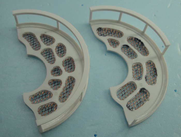
Following the theme of the drive belt shroud I used PE girders to fill the outside round of the flywheel shroud. The bits show the stages of cutting and shaping the segments.
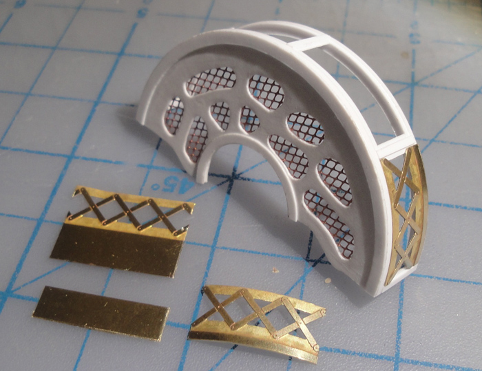
The segments in place affixed with thin CA. At some point I remembered that I could anneal the PE parts to soften them so I did so very carefully since these are thin and easily warped and/or melted. This helped them conform to the curve without tension which is important to avoid warping the thin inner plastic rim.

The lower half of the shroud is the logical place for the frame mounts so here is the beginnings of the plate/cover bit.

I had thought of using sheet brass but it seemed easier to 'slat' the curve with styrene. This will also make it easier to repair/alter sections of it as it evolves.

Outer layer in place. I'm going to glue in an inner layer of slats, let that cure then fill in and strengthen the whole section with thin CA.

I've been tinkering with the shifter as well but there hasn't been enough progress to merit photos, hopefully next week will bring some of those. I've also been having some ideas about the belt drive shroud mounting scheme, finally. My subconscious isn't what it once was, it seems
Nothing exceeds like excess ...
KatsZenJammer- Resident member
- Posts : 2600
Join date : 2016-05-20
Age : 57
Location : Vancouver, BC
Re: Steampunk Harley - Tamiya 1/6 HD FLH Classic 'extreme' kit bash (Very Photo Heavy)
![]() by GaryDainton Wed 10 Jan 2018, 11:57 am
by GaryDainton Wed 10 Jan 2018, 11:57 am
GaryDainton- Advanced Member
- Posts : 4433
Join date : 2014-03-06
Age : 56
Location : Bolton UK
Re: Steampunk Harley - Tamiya 1/6 HD FLH Classic 'extreme' kit bash (Very Photo Heavy)
![]() by Guest Wed 10 Jan 2018, 1:34 pm
by Guest Wed 10 Jan 2018, 1:34 pm
Guest- Guest
Re: Steampunk Harley - Tamiya 1/6 HD FLH Classic 'extreme' kit bash (Very Photo Heavy)
![]() by Geezerman Sat 13 Jan 2018, 11:55 am
by Geezerman Sat 13 Jan 2018, 11:55 am
It's hard to show my admiration for this build, regularly, without getting mushingly redundant !
Geezerman- Advanced Member
- Posts : 3651
Join date : 2013-02-24
Age : 88
Location : Gulf coast of central Florids
Re: Steampunk Harley - Tamiya 1/6 HD FLH Classic 'extreme' kit bash (Very Photo Heavy)
![]() by KatsZenJammer Sun 28 Jan 2018, 10:37 pm
by KatsZenJammer Sun 28 Jan 2018, 10:37 pm
Another posting gap brought on by the ever present stuff, none of it bad or anything. Some work has been accomplished though and every little bit helps in its own way.
Added the 'framing' to the spaces between the PE bits on the flywheel shroud perimeter, this seals in the bits themselves.

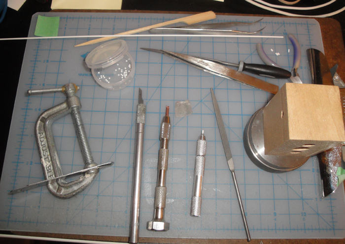
During one of the gap times I started thinking about all the little bits that needed to be produced, which meant a lot of repetitive work. The inspiration was to simply relocate a clipboard with a cutting mat and the stuff I needed to my computer desk, thus allowing me to do some work despite the fact that I wasn't in the hobby room. Here is the set up for producing a whole lot of rivet heads from a 1 mm styrene rod. Hand file the end of the rod to a rough roundness, the cut copper tube is the form for the shaping, the pin vise is to hold the bit of rod, the C clamp is for the gapped cutting blade for uniform depth and the chisel blade X Acto is for final cutting. You can see the rivet heads in the plastic cup. I started referring to this as 'doing some knitting.'
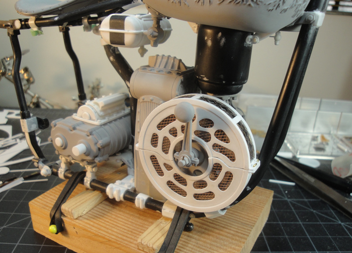
The flywheel shroud after I drilled the mount holes. Its still sitting on the flywheel in this shot - once the frame mounting set up is complete it will sit properly..
Adding some seam coverage to the cover plate. Not absolutely necessary but it does add more detail which is what I'm after. After this I'm thinking of adding some rivets before tackling the frame mounting.

Though I haven't finalized my thinking on the shifter I did add some more surface detail on the top disc.

I also started work on the drive belt shroud frame mounting set up but neglected to document it, not much of a loss because at this time its just some bits added. Once it starts taking shape I'll snap some photos.
I'm going to try and keep focused here - work up the shrouds to the point where they are mounted to the frame and work out the final stuff for the shifter then move onto the water pump and fuel feed throttle. Having just written this I'm quite certain that there will be more distractions and inspirations and other assorted impediments to smooth progress ... what else is new, lol.
Nothing exceeds like excess.
KatsZenJammer- Resident member
- Posts : 2600
Join date : 2016-05-20
Age : 57
Location : Vancouver, BC
Re: Steampunk Harley - Tamiya 1/6 HD FLH Classic 'extreme' kit bash (Very Photo Heavy)
![]() by Geezerman Mon 29 Jan 2018, 11:32 am
by Geezerman Mon 29 Jan 2018, 11:32 am
Geezerman- Advanced Member
- Posts : 3651
Join date : 2013-02-24
Age : 88
Location : Gulf coast of central Florids
Re: Steampunk Harley - Tamiya 1/6 HD FLH Classic 'extreme' kit bash (Very Photo Heavy)
![]() by GaryDainton Wed 31 Jan 2018, 12:21 pm
by GaryDainton Wed 31 Jan 2018, 12:21 pm
GaryDainton- Advanced Member
- Posts : 4433
Join date : 2014-03-06
Age : 56
Location : Bolton UK
Re: Steampunk Harley - Tamiya 1/6 HD FLH Classic 'extreme' kit bash (Very Photo Heavy)
![]() by KatsZenJammer Sun 04 Feb 2018, 5:45 pm
by KatsZenJammer Sun 04 Feb 2018, 5:45 pm
So I had booked some post Birthday time off from the day job for the sheer purpose of resting and recharging. I also set myself the goal of trying to get some level of completion from the trio of parts I've been working on. Having said that this is going to be a somewhat long and wordy post.
I arranged the photos by parts instead of sequentially - that was a bit too confusing. These first couple are of the back side of the shifter where I added mechanical details in the form of nut/bolt combos and a ring to reflect the one on the front side. In the second photo you can also see the addition of some rivet heads on the brackets on the sides.


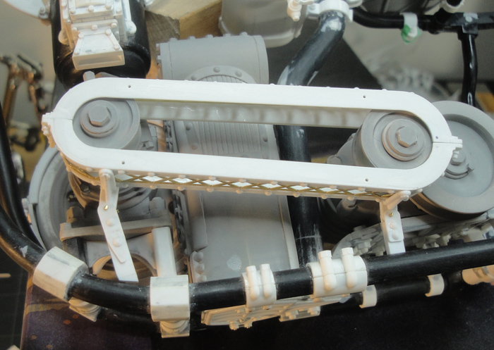
Adding mounts to the primary drive belt shroud/cover. Because of the way this part was made I could not work out a way to make the mount brackets removable from the shroud itself so I chose to affix them and work out a way to make it removable elsewhere.

Shaping and adding support detail (which actually provides support).

U shaped mounts with holes drilled through. This is where the removability will come in but a problem that came up was that I won't be able to drop the part in from the top due to the clearances of the drive belt wheels. Some more thought required.

Roughing out the posts for the mounting - also the angles and locations and all that.

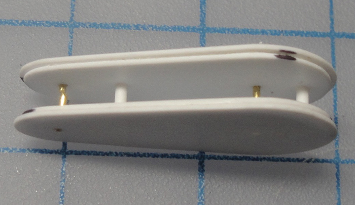
The solution to the mounting angle problem - make the front of the U mount removable. Top left is the original bit which was cut off and the replacement plate was made to seat onto two pins which have been set into the post. This is the longer front post but I managed to do the same with the short rear post as well.

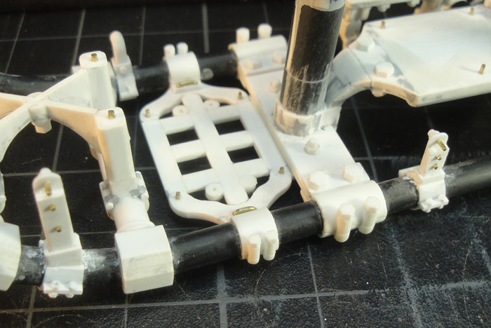
Test fit prior to affixing the posts to the frame.
Affixed to the frame. First step was MEK and minor adjustments before the glue set up. This was followed by reinforcement with careful application of thin CA.

The mounts for the flywheel shroud/cover start taking shape. Also, rivet details have been added at this point.

The rear mount point after development and you can see the front mount points worked up - I kind of forgot to take photos of the in-between phases here.

For the front points I chose to drill into the frame and set pins there. Most of the frame mounting is clamp on bracket style but here,
as with the front mounts on the water and fuel tanks, I'm going with frame points instead of added clamps or stuff.

Once I had the front points set up I was able to work up the rear mount post - here it is in rough form.

Kind of hard to see the rear post but it's there. The front points are going to look like moulded into the frame bits.

So I can say with some degree of satisfaction that I have achieved my basic goals for this week *cheering and revelry*
The follow up to this is going to be adding the clamp bands and stuff to the posts and smoothing out the front frame mount points. As for the Shifter I'm almost at the complete phase, I just want to work up a couple of handles.
It feels good to have gotten through this stuff, the whole mounting thing was becoming a hang up. And as the next steps won't demand serious energy and thought I can start on the last few bits like the water pump set up, the fuel feed throttle and handle and all the plumbing mount points that still need to be created and affixed. Oh, yeah, and a rear view mirror for the right handlebar ...
Nothing exceeds like excess.
KatsZenJammer- Resident member
- Posts : 2600
Join date : 2016-05-20
Age : 57
Location : Vancouver, BC
Re: Steampunk Harley - Tamiya 1/6 HD FLH Classic 'extreme' kit bash (Very Photo Heavy)
![]() by Geezerman Sun 04 Feb 2018, 6:55 pm
by Geezerman Sun 04 Feb 2018, 6:55 pm
Geezerman- Advanced Member
- Posts : 3651
Join date : 2013-02-24
Age : 88
Location : Gulf coast of central Florids
Re: Steampunk Harley - Tamiya 1/6 HD FLH Classic 'extreme' kit bash (Very Photo Heavy)
![]() by KatsZenJammer Mon 26 Feb 2018, 3:38 am
by KatsZenJammer Mon 26 Feb 2018, 3:38 am
Another long posting gap brought on by the blitz of milady's Bday, which happens to be Valentine's Day, followed by a sudden re-familiarization with the technical details of figure skating (something that seems to happen every four years) but some stuff got accomplished despite that.
Looking at the parts one day I realized the fuel tank portion was woefully under embellished so I added some rivet heads in what seemed like the appropriate place. I still want to 'fancy it up a touch' more but am unsure as to how or with what. Likely more to come on this ... later.

The attachment point for the flywheel cover rear brace in place and the clamp band added.

The drive belt cover mounts in place and detailing in the works. On the other side of the frame is the flywheel cover mount point with detailing added.
Starting the water pump assembly with the pump belt cover. Originally this was going to be fully developed, with wheels/cogs and a belt and the cover was going to have cut outs and all, like the larger assemblies already made. Then a voice in my head suggested I make my life easier - enclose it and imply the details.

Test fit of the idea.
Holes for the shafts cut out.

Test fit to check geometry and angles and stuff.


To hide the fact that there's nothing inside the cover will sit close to the tranny to obscure the view. The same tactic will be used to obscure the top hole where the water pump will be attached. The water pump has not yet been started - still mulling over options. The 'fuel throttle' lives in limbo as well, but both of those parts won't be hugely complex so I'm hoping for a quick turn over. Then comes the blitz of detail stuff I've been putting off ...
Nothing exceeds like excess.
KatsZenJammer- Resident member
- Posts : 2600
Join date : 2016-05-20
Age : 57
Location : Vancouver, BC
Re: Steampunk Harley - Tamiya 1/6 HD FLH Classic 'extreme' kit bash (Very Photo Heavy)
![]() by Guest Mon 26 Feb 2018, 12:16 pm
by Guest Mon 26 Feb 2018, 12:16 pm

Guest- Guest
Re: Steampunk Harley - Tamiya 1/6 HD FLH Classic 'extreme' kit bash (Very Photo Heavy)
![]() by Mr Hirakawa Mon 26 Feb 2018, 2:17 pm
by Mr Hirakawa Mon 26 Feb 2018, 2:17 pm

Mr Hirakawa- Resident member
- Posts : 1524
Join date : 2015-11-11
Age : 52
Re: Steampunk Harley - Tamiya 1/6 HD FLH Classic 'extreme' kit bash (Very Photo Heavy)
![]() by Geezerman Mon 26 Feb 2018, 4:30 pm
by Geezerman Mon 26 Feb 2018, 4:30 pm
Geezerman- Advanced Member
- Posts : 3651
Join date : 2013-02-24
Age : 88
Location : Gulf coast of central Florids
Re: Steampunk Harley - Tamiya 1/6 HD FLH Classic 'extreme' kit bash (Very Photo Heavy)
![]() by GaryDainton Tue 27 Feb 2018, 1:44 pm
by GaryDainton Tue 27 Feb 2018, 1:44 pm
GaryDainton- Advanced Member
- Posts : 4433
Join date : 2014-03-06
Age : 56
Location : Bolton UK
Re: Steampunk Harley - Tamiya 1/6 HD FLH Classic 'extreme' kit bash (Very Photo Heavy)
![]() by KatsZenJammer Sun 04 Mar 2018, 6:46 pm
by KatsZenJammer Sun 04 Mar 2018, 6:46 pm
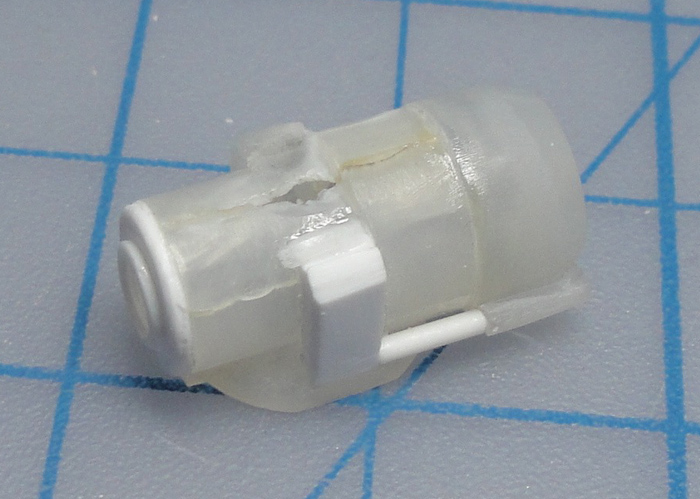
Once the water pump pulley cover was mostly built up I started in on the water pump itself. In the end I chose to kit bash the original carburetor and re-purpose it to this application. First step was to separate carburetor parts and start hacking and chopping.

The parts once they've been 'scoured' of unwanted details.

The proto-pump takes shape with parts affixed and a shaft in place.

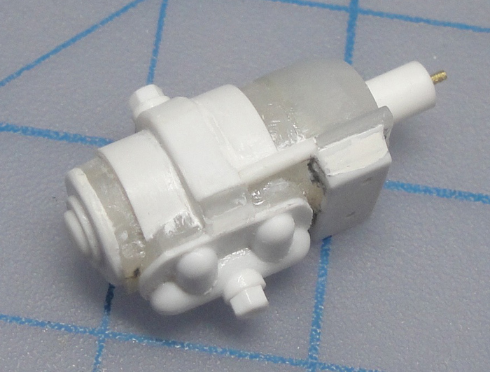
Adding bits to make the pump more symmetrical.
And as it stands at the moment. There is still a bit more work to do to the pump prior to working up the frame mounting set up but this gives the basic idea of what will be going on.

I must admit that I'm feeling weird at this point in the build - the water pump is the second to last 'mechanical' part which I have to make. After this much time getting to this point is kind of disconcerting to say the least. Oh, there is still a lot of work to be done, the fuel throttle is kind of the last part and that will be followed by all the plumbing connection points, things like the brake cable set points, the foot pegs, foot brake lever and the Rear View Mirror. Then comes knobs and handles for the shift and throttle levers and the still daunting task of working up the dials for the instrument panel. There will also be 'embellishment' along the plumbing as well ... so maybe I'm not that close to the end of the construction process.
Having said that, the time is approaching where most of the rest of the build will involve having large portions of the whole test fitted in order to make the last few bits - that ought to provide more interesting photographic opportunities to say the least.
Of course I could dwell on the 'accessorizing' I want to do - tool kit and tools, gloves and goggles, operational equipment like the little torch for firing of the boiler and stuff like that - or I could dredge up the potential for a flat diorama display base which I've been considering.
Or I could just file everything away until I've completed the water pump and get it mounted, lol.
Nothing exceeds like excess.
KatsZenJammer- Resident member
- Posts : 2600
Join date : 2016-05-20
Age : 57
Location : Vancouver, BC
Re: Steampunk Harley - Tamiya 1/6 HD FLH Classic 'extreme' kit bash (Very Photo Heavy)
![]() by GaryDainton Mon 05 Mar 2018, 1:36 pm
by GaryDainton Mon 05 Mar 2018, 1:36 pm
https://www.ebay.com/sch/i.html?_from=R40&_trksid=p2380057.m570.l1313.TR12.TRC2.A0.H0.X1%2F6+scale.TRS0&_nkw=1%2F6+scale&_sacat=0
Catch a load of this.....
https://www.ebay.com/itm/1-6-Scale-Lighter-Cigarette-Set-for-12-Action-Figure-Toys/362259393897?hash=item545857ad69:g:ZyIAAOSwEoxanCMX
GaryDainton- Advanced Member
- Posts : 4433
Join date : 2014-03-06
Age : 56
Location : Bolton UK
Re: Steampunk Harley - Tamiya 1/6 HD FLH Classic 'extreme' kit bash (Very Photo Heavy)
![]() by Geezerman Tue 13 Mar 2018, 9:08 am
by Geezerman Tue 13 Mar 2018, 9:08 am
Geezerman- Advanced Member
- Posts : 3651
Join date : 2013-02-24
Age : 88
Location : Gulf coast of central Florids
Re: Steampunk Harley - Tamiya 1/6 HD FLH Classic 'extreme' kit bash (Very Photo Heavy)
![]() by KatsZenJammer Sat 24 Mar 2018, 6:38 pm
by KatsZenJammer Sat 24 Mar 2018, 6:38 pm
Gary - thanks for the links, I've been considering bashing some pre-existant stuff for the accessorizing and hadn't thought of eBay due to a personal blind spot as far as utilizing on line resources (translation: I'm not keeping current and fall back on old fashioned thinking, lol).
Some sad news to explain my recent absence - right after my last post in this thread the health of my 16 year old kitty took a nose dive, that was March 4th. Milady took her (the cat) to the vet on March 5 (Monday) for blood tests and we returned the next day for possible X-rays. It was at that time it was discovered that Mezumi (the kitty) had developed one of the many forms of feline cancer that strikes older cats with regularity.
So, faced with a choice between artificially extending her life by a month or two of increasing discomfort or dealing with it we chose to go the unpleasant but humane route and had her put down. Sixteen years is a good, long life for a cat and she'd been with us since she was a kitten so it was tough but it was the only viable choice for us - neither of us wanted her to suffer any longer than she had already.
So, sad but very much a part of life and the grieving and mourning period has been enough to allow me to get back into the swing of things. I'm keeping my avatar pic the same as it was as a tribute to her - I had been tempted to change it initially but now my thoughts have shifted to the memorial side of things.
And the return to building wasn't immediate but things have happened. Here's the water pump drive pulley cover with additional detailing added.

The water pump being further developed.

Getting ready to make the support brace - some test fits to give an idea of how the pump will sit in amongst the other parts.


The proto-support piece. Instead of trying to cut the double curve in one piece I used some cut off bits from earlier circles to form the shape.

The support with detail added. After a lot of fiddling I went with a detachable support for ease of painting and installation.

The water pump gets more detail. Though the intake (on top) stayed the same I shifted the outflow connector after the next picture was taken.
Test fit with old outflow connector placement.

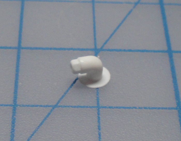
The boiler/burner water intake connector. I forgot to take photos of the raw making part.
Test fit - you can see that the boiler/burner is now getting some long awaited finalizing work done.

Test fit - the pulley cover with nut/bolt detailing added, the water pump outflow connector in it's new place and the boiler/burner ignition port cover piece sits below the intake connector.

Here you can see the relocated outflow point and some additional added details to the water pump. At this point I'm thinking this part is mostly done - maybe a bit more detailing could happen but nothing concrete has been jumping up at me.

And so it is with a weird sense of anticipation mixed with anxiety that I can declare that all the Main Parts of the steamcycle have been built. Now comes the extra bits which are essential but part of another part. These include the fuel feed/throttle assembly, the adding of dials to the console, foot pegs and rear brake foot lever, a tensioning roller for the secondary drive belt, the primary and secondary drive belts themselves, a rear view mirror for the right side handlebar, and at least one other thing that has slipped my mind. All of this followed by, or concurrent with, plumbing.
Much of me is tempted to start diving into the paint aspect with full force but I must wait, I must. I will definitely be shooting primer at the stuff that hasn't already been shot but I am forcing myself to hold off on the 'real' painting until everything is in its place to avoid any errors caused by jumping the gun and so forth. Plus there's the fact that my workspace is quite constrained and trying to build and paint at the same time isn't possible under the circumstances.
Nothing exceeds like excess ...
KatsZenJammer- Resident member
- Posts : 2600
Join date : 2016-05-20
Age : 57
Location : Vancouver, BC
Re: Steampunk Harley - Tamiya 1/6 HD FLH Classic 'extreme' kit bash (Very Photo Heavy)
![]() by Speed Racer 65 Sat 24 Mar 2018, 7:47 pm
by Speed Racer 65 Sat 24 Mar 2018, 7:47 pm

Speed Racer 65- Intermediate Member

- Posts : 865
Join date : 2015-08-06
Location : Louisville KY
Re: Steampunk Harley - Tamiya 1/6 HD FLH Classic 'extreme' kit bash (Very Photo Heavy)
![]() by kpnuts Sat 24 Mar 2018, 8:00 pm
by kpnuts Sat 24 Mar 2018, 8:00 pm
kpnuts- Resident member
- Posts : 1676
Join date : 2015-01-29
Re: Steampunk Harley - Tamiya 1/6 HD FLH Classic 'extreme' kit bash (Very Photo Heavy)
![]() by Sponsored content
by Sponsored content
Sponsored content
Page 17 of 25 • 1 ... 10 ... 16, 17, 18 ... 21 ... 25 ![]()
» Tamiya 1/6 Harley Davidson Fat Boy Lo
» Tamiya 1/6 Harley Davidson FLH1200
» Steampunk Ducati
» '57 Salvage bash-up
|
|
|