Steampunk Harley - Tamiya 1/6 HD FLH Classic 'extreme' kit bash (Very Photo Heavy)
Page 7 of 25 •  1 ... 6, 7, 8 ... 16 ... 25
 ![]()
Re: Steampunk Harley - Tamiya 1/6 HD FLH Classic 'extreme' kit bash (Very Photo Heavy)
![]() by Guest Mon 18 Jul 2016, 5:59 pm
by Guest Mon 18 Jul 2016, 5:59 pm
Guest- Guest
Re: Steampunk Harley - Tamiya 1/6 HD FLH Classic 'extreme' kit bash (Very Photo Heavy)
![]() by KatsZenJammer Sun 24 Jul 2016, 8:40 pm
by KatsZenJammer Sun 24 Jul 2016, 8:40 pm

Well, the back twinges kept me from fully devoting my time to the hobby room but I did manage to get some stuff moving. I also discovered that my inner fan boy is still quite capable of binge watching old TV ... but that's another story (and Gary, I'd love to help on your Voyager but my rate of building is so slow I'd be setting you back quite a bit, lol)
We start this post with the eccentric rod shroud getting some fill to create the 'slot.'

Test fit.
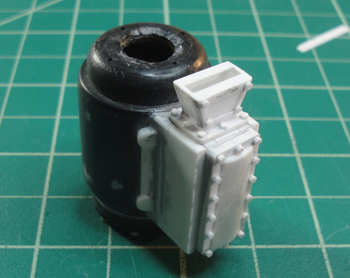
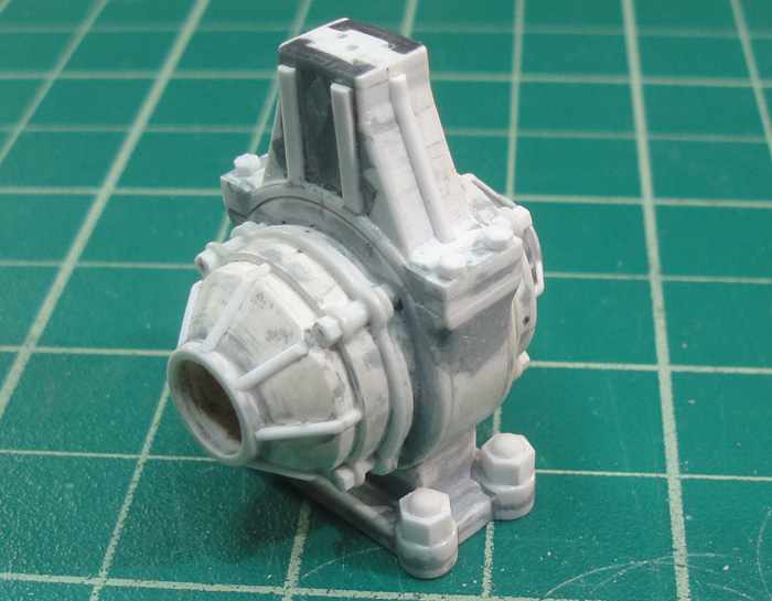
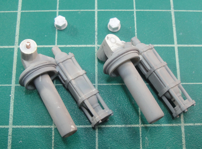
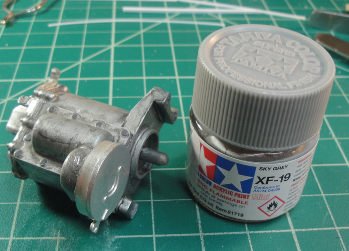
The crankcase is pretty much complete as far as building goes, the connecting rod mount 'bolts' are in place and then the big mounting nuts are added to the base.

Not easy to see here but I added some hex nuts to the hinges of the post mounts. There's still the question of if I want to 'split' the clamp portions or not, the jury's still out on that one.
More Hex Nuts! The steam chest starts to look even more nubbly than before.

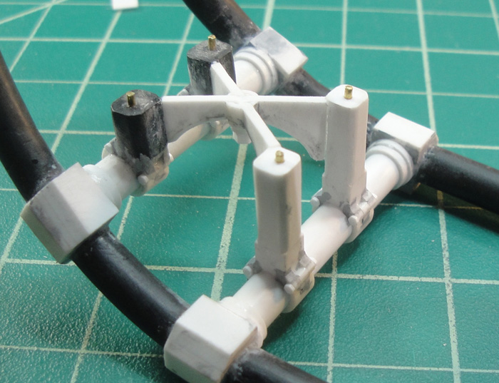
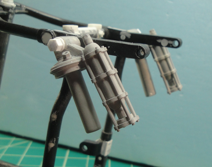
At some point I dropped the bike frame and snapped off one of the plastic guide posts for the rear shocks. Putting my mind as to how I could repair it I suddenly remembered that those plastic posts were just temporary ones and that I had wanted to replace them with metal ones. So here's the start of that, which involved filling in the existing holes and drilling them out for the metal posts. Also, I added More Hex Nuts.
Test fit and the sudden realization that I had forgotten to account for the rear fender mount extensions so I had to make new posts.
A view of my updated version of achieving a consistent cut from small rod. Same idea as before but now using an aluminum plate for the base and spark plug gapping guides made from steel. Also shown are the Hex Nuts for the bottom portion of the shocks.

Test fit with all the parts accounted for, lol.

I've also started modding the chain sprockets to convert them to belt drive. And I've been putting my mind to the next steps in the drive train as it feeds off the crankshaft. At this rate I should be getting ready to paint for real around 2025 or so


KatsZenJammer- Resident member

- Posts : 2600
Join date : 2016-05-20
Age : 57
Location : Vancouver, BC
Re: Steampunk Harley - Tamiya 1/6 HD FLH Classic 'extreme' kit bash (Very Photo Heavy)
![]() by GaryDainton Sun 24 Jul 2016, 8:44 pm
by GaryDainton Sun 24 Jul 2016, 8:44 pm

GaryDainton- Advanced Member
- Posts : 4433
Join date : 2014-03-06
Age : 56
Location : Bolton UK
Re: Steampunk Harley - Tamiya 1/6 HD FLH Classic 'extreme' kit bash (Very Photo Heavy)
![]() by Skid Sun 24 Jul 2016, 10:52 pm
by Skid Sun 24 Jul 2016, 10:52 pm
Could you explain how your jig thingummie works please?
_________________
Al.
Constructive criticism is always welcome.
“Success always demands a greater effort.” Winston Churchill
"Success is failure turned inside out" Unknown

Skid- Admin
- Posts : 7129
Join date : 2013-02-15
Age : 75
Location : Newcastle. Good Old Blighty. -

Re: Steampunk Harley - Tamiya 1/6 HD FLH Classic 'extreme' kit bash (Very Photo Heavy)
![]() by Geezerman Tue 26 Jul 2016, 11:30 am
by Geezerman Tue 26 Jul 2016, 11:30 am


Geezerman- Advanced Member
- Posts : 3651
Join date : 2013-02-24
Age : 88
Location : Gulf coast of central Florids
Re: Steampunk Harley - Tamiya 1/6 HD FLH Classic 'extreme' kit bash (Very Photo Heavy)
![]() by Guest Tue 26 Jul 2016, 11:50 am
by Guest Tue 26 Jul 2016, 11:50 am
Guest- Guest
Re: Steampunk Harley - Tamiya 1/6 HD FLH Classic 'extreme' kit bash (Very Photo Heavy)
![]() by KatsZenJammer Mon 01 Aug 2016, 10:49 pm
by KatsZenJammer Mon 01 Aug 2016, 10:49 pm
Al - the jig is an evolution of a way I found to make uniform bits of the same size, in my case, hex nuts, lol. This iteration involves a flat plate as a base (aluminum in the example I've given), a clamp, an X-Acto blade and a multi-depth steel gapping guide set normally used for spark plugs. Simply, I find the right 'gap shim' and clamp the blade down. The metal base plate prevents 'sink down' into the cutting mat, something that is bound to happen in warm conditions. Then I just 'roll' the piece along the blade to scribe in a guide line. From there I finish the cut by hand. I first used this method years ago, for what I forget, and recently I used a variant of this method to cut down the depth of the big flywheel. This is a good method for those times when you need lots of pieces of the same size ... like hex nuts ...
Well it's been an eventful and busy week so I haven't gotten that much done, what else is new, lol. But I have begun the process of making the drive train.
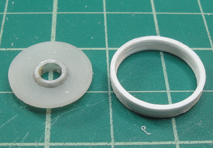
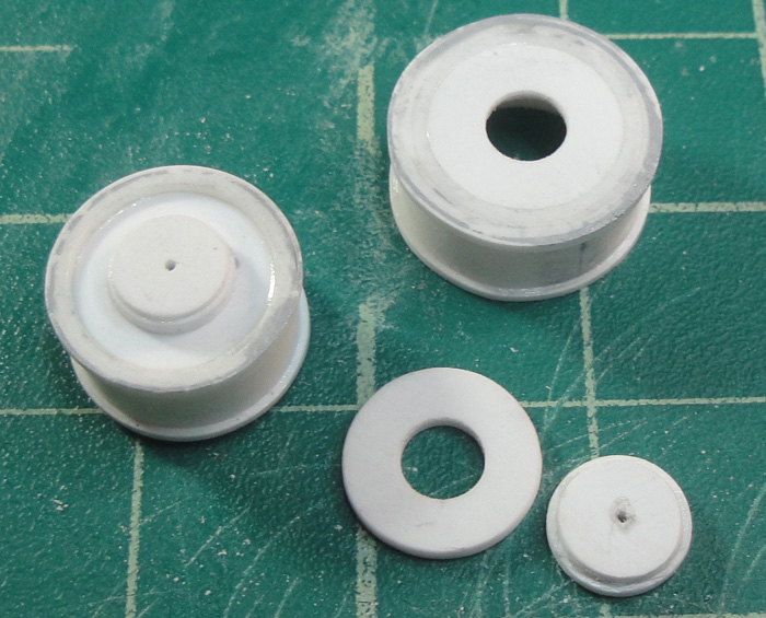
To begin this next phase I start with the primary belt drive wheel for the crankshaft. The tube portion is 1/2 inch styrene and the doughnuts are cut from styrene sheet using a drafting compass.

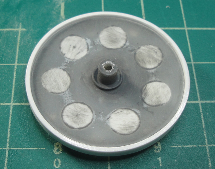
Added some 'shims' between the doughnuts and filed/sanded them to fit inside the tube. I chose to go this way instead of just a single piece doughnut for stability.
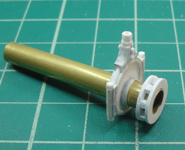
Test fit and a proof of concept examination.

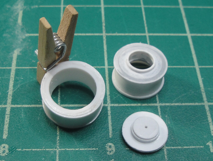
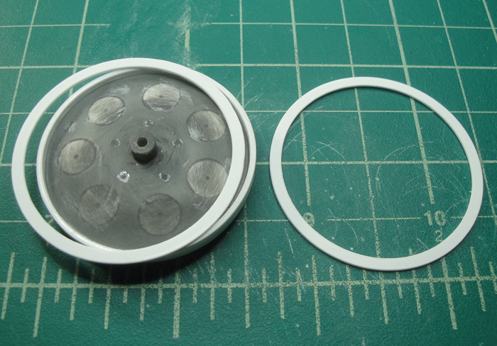
Developing the outside cap for the belt drive wheel and adding a 'rim edge' to the wheel. The round bit in the centre of the solid round plate is for the inside, to fit onto the end of the crank shaft tube. The thicker round bit will sit on the outside of the cap and detailed with ... hex nuts


Another test fit, the outside cap hasn't been detailed yet.

From here I will be making the other wheel for the primary belt drive then modding the kit chain sprockets to convert them to belt drive as well. There is also the adding of 'teeth' to the belt drive wheels, I'm mulling over various methods by which to accomplish this and keep it in scale. And I'm also considering the 'cheat' method of only scribing the 'teeth' which will show once the belt is in place. The belts themselves will be made to look like leather as Victorian era rubber technology wasn't up to it but how I'm going to make the belts is also still under consideration.
Then comes the CV Transmission and once I've got a rough idea of how the whole drive train set up will sit I can start planning how to cram all the other parts in. Stuff like the boiler, water tank, fuel tank, water pump, steam condenser and recirc system can only start happening once I know how much room I have to work with.
Just keep swimming ...
KatsZenJammer- Resident member
- Posts : 2600
Join date : 2016-05-20
Age : 57
Location : Vancouver, BC
Re: Steampunk Harley - Tamiya 1/6 HD FLH Classic 'extreme' kit bash (Very Photo Heavy)
![]() by GaryDainton Tue 02 Aug 2016, 7:10 am
by GaryDainton Tue 02 Aug 2016, 7:10 am
http://italianhorses.net/Tutorials/Leather%20101/lthr.htm
GaryDainton- Advanced Member
- Posts : 4433
Join date : 2014-03-06
Age : 56
Location : Bolton UK
Re: Steampunk Harley - Tamiya 1/6 HD FLH Classic 'extreme' kit bash (Very Photo Heavy)
![]() by KatsZenJammer Sun 07 Aug 2016, 10:42 pm
by KatsZenJammer Sun 07 Aug 2016, 10:42 pm
Having started on the primary drive belt wheels I figured I might as well work up the final drive wheels as well. You can see the 'thickened' tube to the upper right which is for the primary drive at the transmission. The rear chain sprocket wheel from the kit has been de-toothed and thus I return to the kit bash realm. To make the rim I cut three rings from 1mm sheet styrene using a drafting compass.

Glueing the rings together wasn't difficult, merely a bit touchy. I left them mostly 'dirty' except for the joins.

And here's the transmission final drive sprocket modded and with the rim formed just like the rear belt wheel.
The primary drive wheels, crankshaft wheel with the 'back' in place and the transmission wheel waiting for the channel edges.

To smooth out the surface of the rims I laid down strips cut from 0.25 mm sheet styrene and glued them down. After some cleaning came the test fits.

Back to the primary drive wheels. The crankshaft wheel 'cap' still waits for hex nuts and the transmission wheel starts developing the channel edges.
Because the rims for the final drive wheels are so narrow I chose to cut rings from 0.75 sheet to make the channel edges, or sides in this case. Again using the drafting compass method.
I'm not sure if the final drive belt wheels are 'thick' enough for the size of the bike and all that, right now I'm thinking I might add an additional 1mm to each to make a 4mm belt which scales up to about an inch. Given that motorcycle drive chains can be 3/4 of an inch wide this only makes sense. But I'm not going to dwell too much on the physics (thanks to Geezerman for reminding me of that option, lol) and instead just try to make it 'look' realistic.
Just keep swimming ...
KatsZenJammer- Resident member
- Posts : 2600
Join date : 2016-05-20
Age : 57
Location : Vancouver, BC
Re: Steampunk Harley - Tamiya 1/6 HD FLH Classic 'extreme' kit bash (Very Photo Heavy)
![]() by harron68 Mon 08 Aug 2016, 1:31 am
by harron68 Mon 08 Aug 2016, 1:31 am
harron68- Advanced Member
- Posts : 3616
Join date : 2013-02-28
Age : 73
Location : MIDWEST
Re: Steampunk Harley - Tamiya 1/6 HD FLH Classic 'extreme' kit bash (Very Photo Heavy)
![]() by Guest Mon 08 Aug 2016, 2:01 am
by Guest Mon 08 Aug 2016, 2:01 am
Last edited by Plastic Freak on Wed 10 Aug 2016, 12:59 pm; edited 1 time in total
Guest- Guest
Re: Steampunk Harley - Tamiya 1/6 HD FLH Classic 'extreme' kit bash (Very Photo Heavy)
![]() by GaryDainton Mon 08 Aug 2016, 7:41 am
by GaryDainton Mon 08 Aug 2016, 7:41 am
GaryDainton- Advanced Member
- Posts : 4433
Join date : 2014-03-06
Age : 56
Location : Bolton UK
Re: Steampunk Harley - Tamiya 1/6 HD FLH Classic 'extreme' kit bash (Very Photo Heavy)
![]() by Geezerman Wed 10 Aug 2016, 11:06 am
by Geezerman Wed 10 Aug 2016, 11:06 am

Geezerman- Advanced Member
- Posts : 3651
Join date : 2013-02-24
Age : 88
Location : Gulf coast of central Florids
Re: Steampunk Harley - Tamiya 1/6 HD FLH Classic 'extreme' kit bash (Very Photo Heavy)
![]() by disabled modeler Wed 10 Aug 2016, 12:20 pm
by disabled modeler Wed 10 Aug 2016, 12:20 pm
disabled modeler- Intermediate Member

- Posts : 979
Join date : 2016-05-22
Age : 60
Location : Quincy,IL. USA
Re: Steampunk Harley - Tamiya 1/6 HD FLH Classic 'extreme' kit bash (Very Photo Heavy)
![]() by Guest Wed 10 Aug 2016, 6:24 pm
by Guest Wed 10 Aug 2016, 6:24 pm
Guest- Guest
Re: Steampunk Harley - Tamiya 1/6 HD FLH Classic 'extreme' kit bash (Very Photo Heavy)
![]() by KatsZenJammer Sun 14 Aug 2016, 7:34 pm
by KatsZenJammer Sun 14 Aug 2016, 7:34 pm
Buck - I started this mess on May 28th or 29th, 2014 so it's been just over 2 years as of now, lol.
So, working up the final drive belt wheels. I've added a touch of thickness to the width to make the drive belt width a bit closer to what would be needed in a 'real' application.

The primary drive belt wheels in process. The crankshaft drive wheel cap is now in place and the transmission wheel gets putty.

What used to be the rear wheel chain sprocket now looks a lot like a rear wheel belt wheel.

The final drive transmission wheel channel edges about to be affixed.

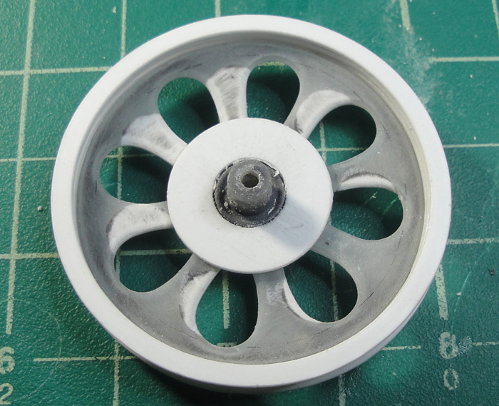
Getting back to the big belt wheel - time for cut outs. Here I used a paper template to give me a guide for the initial lines. This was followed by some freehanding for the final shapes.
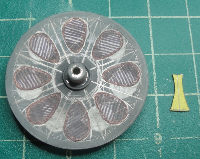
Initial cut out, doing it 'small' to allow for precise shaping.

And after some more shaping. Gotta love the Dremel flex tool.

Testing the fit and checking a lot of other things. Main concern here is to insure that when I set the belt guide to the inner wheel it is aligned to keep the belt clear of the edge of the tyre itself. But I also discovered that I cut out too much and you can see the rear wheel axle hub so that means ...
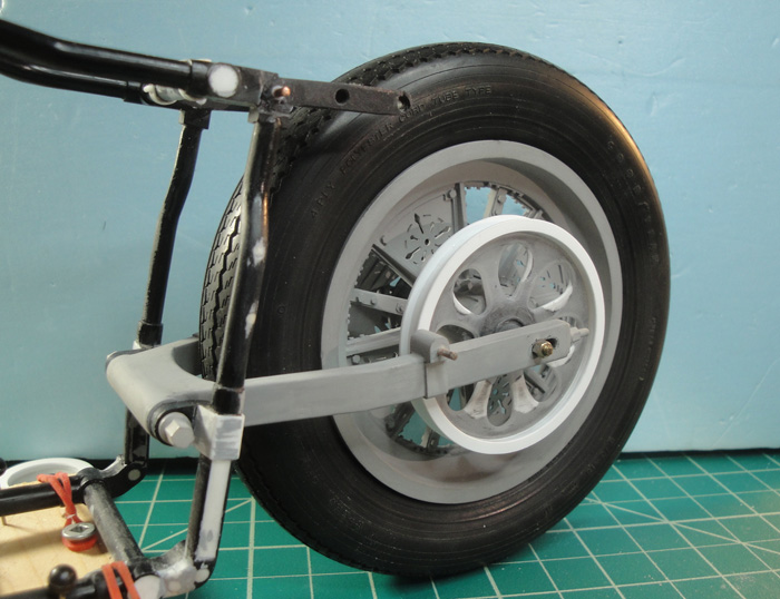
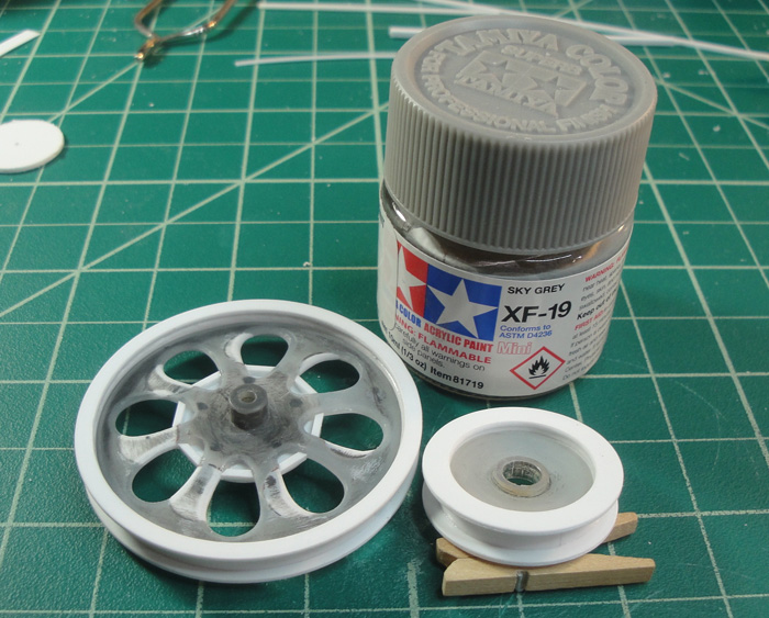
... Cutting a ring that matches the axle hub. This will be followed by more modding but for now it's enough that I totally forgot to take this into account whilst happily grinding away with the Dremel.
The issue with the belt drive wheel isn't a horrible thing as I was planning to add more detail to it anyway. This just means I have to re-think the way I was going to add details in order to accommodate the hub cover ring.
Just keep swimming ...
KatsZenJammer- Resident member
- Posts : 2600
Join date : 2016-05-20
Age : 57
Location : Vancouver, BC
Re: Steampunk Harley - Tamiya 1/6 HD FLH Classic 'extreme' kit bash (Very Photo Heavy)
![]() by Geezerman Mon 15 Aug 2016, 11:23 am
by Geezerman Mon 15 Aug 2016, 11:23 am

Geezerman- Advanced Member
- Posts : 3651
Join date : 2013-02-24
Age : 88
Location : Gulf coast of central Florids
Re: Steampunk Harley - Tamiya 1/6 HD FLH Classic 'extreme' kit bash (Very Photo Heavy)
![]() by disabled modeler Mon 15 Aug 2016, 11:59 am
by disabled modeler Mon 15 Aug 2016, 11:59 am
.....simply stunning work....I could never be that talented or skilled to do the work you have done on it. its going to be a real master piece.
disabled modeler- Intermediate Member
- Posts : 979
Join date : 2016-05-22
Age : 60
Location : Quincy,IL. USA
Re: Steampunk Harley - Tamiya 1/6 HD FLH Classic 'extreme' kit bash (Very Photo Heavy)
![]() by Guest Mon 15 Aug 2016, 1:15 pm
by Guest Mon 15 Aug 2016, 1:15 pm
Guest- Guest
Re: Steampunk Harley - Tamiya 1/6 HD FLH Classic 'extreme' kit bash (Very Photo Heavy)
![]() by KatsZenJammer Sun 28 Aug 2016, 10:18 pm
by KatsZenJammer Sun 28 Aug 2016, 10:18 pm
A bit of a gap in posting for me due to scheduling conflicts (things got busy, lol). Bits of work occurred but another part of the stall out was that I got inspired to start on the transmission. Having said that ...
A look at the final drive wheels/cogs. The back of the 'wheel' cog filled in with strips to fill in the gap behind the hub ring. The 'transmission' cog test fit.
The original kit transmission being readied to become a Steampunk CVT. This is going to be an exercise in free form forming as I have no real idea how it should look.


Adding more of a curve to one side. I started with 1/2 inch styrene tube, cut that in half, added a thin sheet of styrene to the outside then spread the piece to both widen the base and flatten the curve of the tube. Seams are joined with MEK first followed by reinforcing with thin CA.

The cover plate for the kit tranny being modified, starting with the removal of the oil reservoir. The strips you see on the tranny body are to level the edges, the one part didn't quite match the other.

Returning to the primary drive wheels/cogs the work on the CVT has allowed me to establish the diameter of the shaft which allowed for making the inner plates which fill the transmission wheel. I've included the crankshaft wheel for visual comparison.
And the plodding on continues.
Also, Mark, thanks again for your very kind words but I have to say that I regularly think the same about myself (that I could never be as good at them) in comparison to others work. It took me a while to realize that the reason I felt that way was because I was looking at the work of others, who were expressing/exercising their own unique approaches and skills. No matter how much practice I get in, no matter what new things I absorb and incorporate, I'm always stunned by what other people are doing and feel I could never be that good. And that is because I'm not them, and the best that I can do is the best I can do, not the best that others can do. This keeps me going, chasing after that which is inherently unattainable (like trying to be perfect), and the effort of the chase helps me get 'better'.
Finally, your work gives me that feeling regularly, lol. So right back at ya
KatsZenJammer- Resident member
- Posts : 2600
Join date : 2016-05-20
Age : 57
Location : Vancouver, BC
Re: Steampunk Harley - Tamiya 1/6 HD FLH Classic 'extreme' kit bash (Very Photo Heavy)
![]() by disabled modeler Mon 29 Aug 2016, 12:48 am
by disabled modeler Mon 29 Aug 2016, 12:48 am
disabled modeler- Intermediate Member
- Posts : 979
Join date : 2016-05-22
Age : 60
Location : Quincy,IL. USA
Re: Steampunk Harley - Tamiya 1/6 HD FLH Classic 'extreme' kit bash (Very Photo Heavy)
![]() by GaryDainton Mon 29 Aug 2016, 8:57 am
by GaryDainton Mon 29 Aug 2016, 8:57 am
GaryDainton- Advanced Member
- Posts : 4433
Join date : 2014-03-06
Age : 56
Location : Bolton UK
Re: Steampunk Harley - Tamiya 1/6 HD FLH Classic 'extreme' kit bash (Very Photo Heavy)
![]() by Skid Mon 29 Aug 2016, 9:46 am
by Skid Mon 29 Aug 2016, 9:46 am
Wonderful stuff!!!
_________________
Al.
Constructive criticism is always welcome.
“Success always demands a greater effort.” Winston Churchill
"Success is failure turned inside out" Unknown
Skid- Admin
- Posts : 7129
Join date : 2013-02-15
Age : 75
Location : Newcastle. Good Old Blighty. -
Re: Steampunk Harley - Tamiya 1/6 HD FLH Classic 'extreme' kit bash (Very Photo Heavy)
![]() by Guest Mon 29 Aug 2016, 6:03 pm
by Guest Mon 29 Aug 2016, 6:03 pm

Guest- Guest
Re: Steampunk Harley - Tamiya 1/6 HD FLH Classic 'extreme' kit bash (Very Photo Heavy)
![]() by Geezerman Wed 31 Aug 2016, 10:31 am
by Geezerman Wed 31 Aug 2016, 10:31 am
Geezerman- Advanced Member
- Posts : 3651
Join date : 2013-02-24
Age : 88
Location : Gulf coast of central Florids
Re: Steampunk Harley - Tamiya 1/6 HD FLH Classic 'extreme' kit bash (Very Photo Heavy)
![]() by Sponsored content
by Sponsored content
Sponsored content
Page 7 of 25 • 1 ... 6, 7, 8 ... 16 ... 25 ![]()
» Tamiya 1/6 Harley Davidson Fat Boy Lo
» Tamiya 1/6 Harley Davidson FLH1200
» Steampunk Ducati
» '57 Salvage bash-up
|
|
|